Solar panel

a solar panel and solar panel technology, applied in the field of solar panels, can solve the problems of increasing the manufacturing cost of the protection plate, adversely affecting the aesthetic appeal, and increasing the manufacturing cost of the solar panel, so as to improve the aesthetic appeal and reduce the manufacturing cos

Active Publication Date: 2019-02-12
TOYOTA IND CORP +1
View PDF6 Cites 1 Cited by
  • Summary
  • Abstract
  • Description
  • Claims
  • Application Information

AI Technical Summary

Benefits of technology

[0005]It is an object of the present invention to provide a solar panel that improves the aesthetic appeal and decreases the manufacturing cost.

Problems solved by technology

This adversely affects the aesthetic appeal.
However, manufacturing of the conventional solar panel requires a process for preparing a transparent protection plate formed from inorganic glass and a process for applying opaque paint to the necessary portions of the protection plate.
This increases the manufacturing cost of the protection plate and thus increases the manufacturing cost of the solar panel.

Method used


Image

  • Solar panel
  • Solar panel
  • Solar panel

Examples


first embodiment

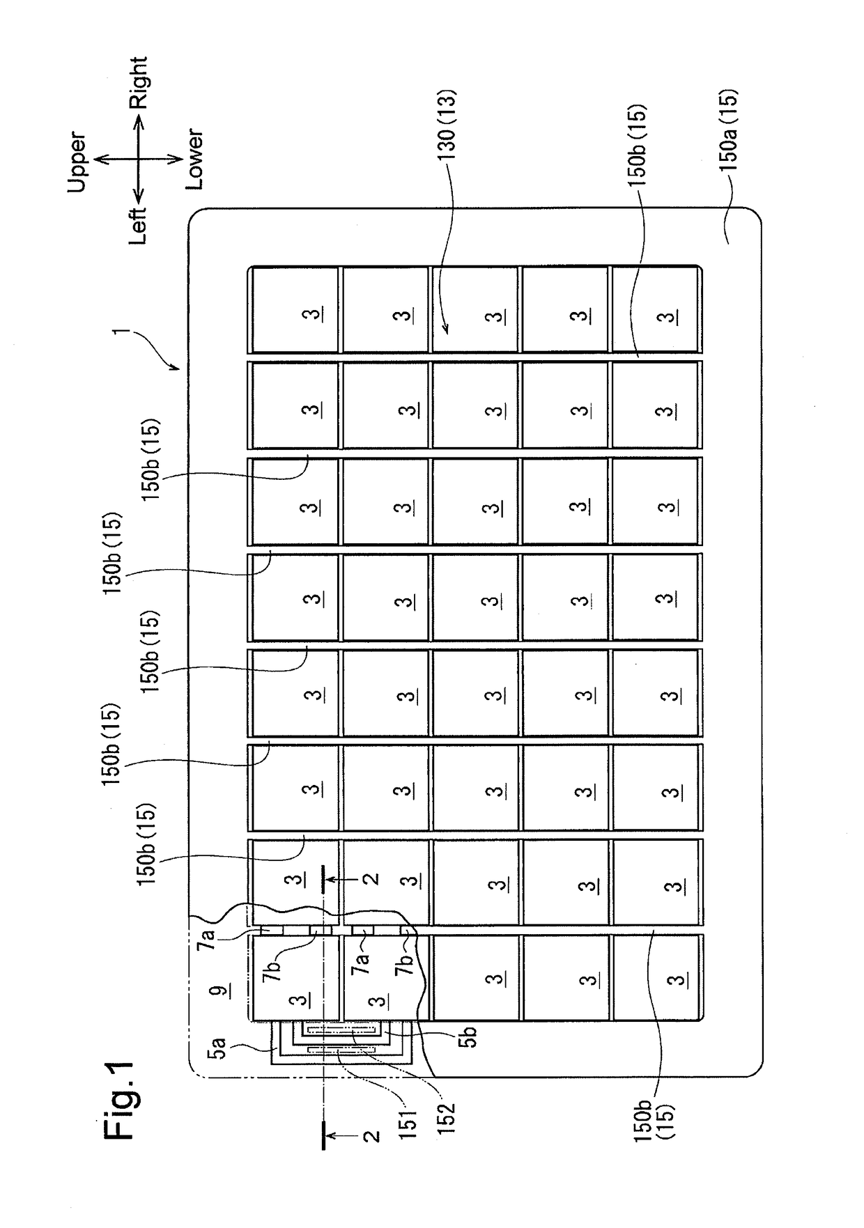
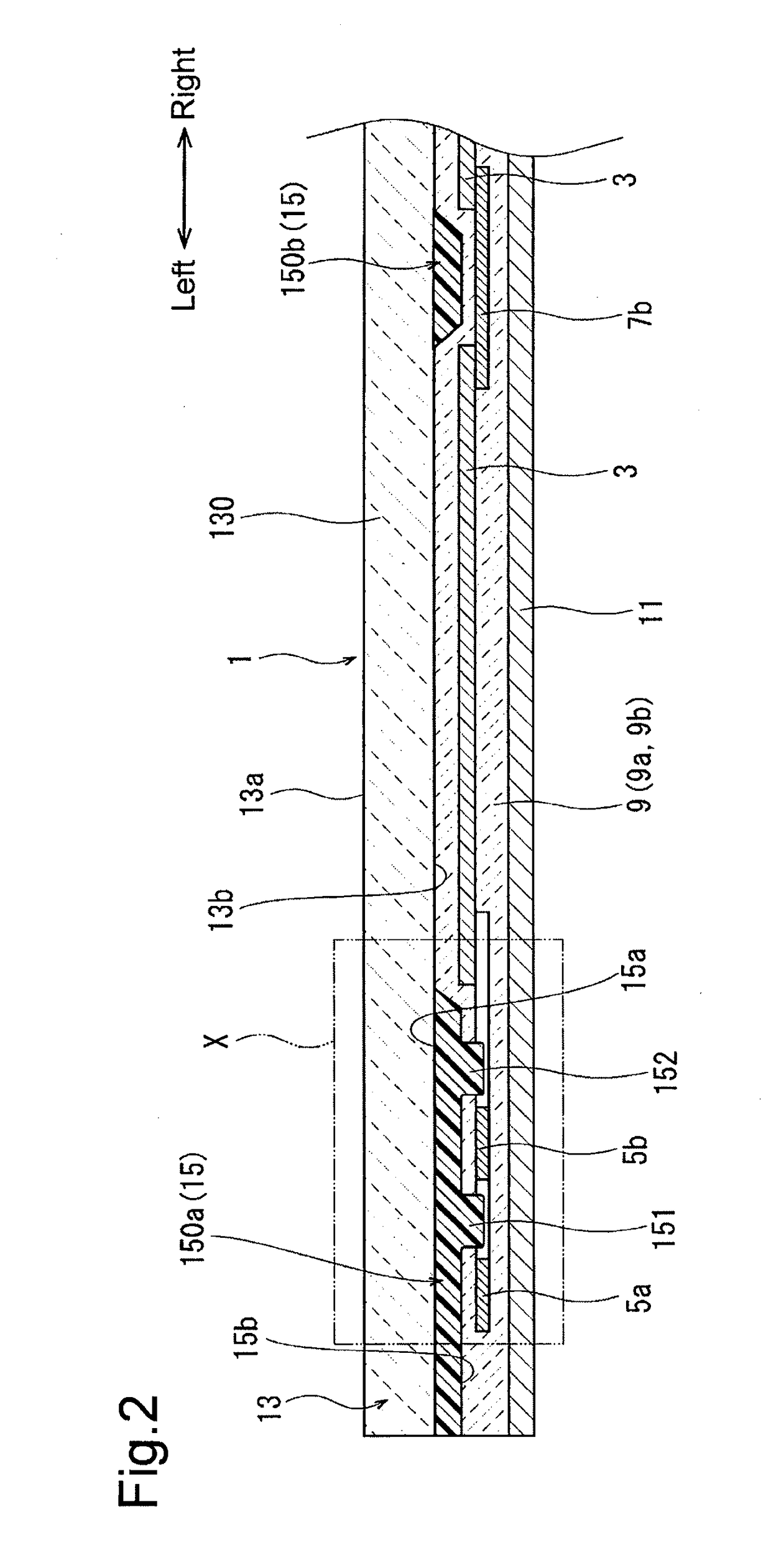
[0015]As shown in FIGS. 1 and 2, a solar panel of the first embodiment includes a protection plate 1, photovoltaic battery cells 3, tab wires 5a and 5b, interconnectors 7a and 7b, an encapsulant 9, and a back panel 11. The tab wires 5a and 5b and the interconnectors 7a and 7b correspond to conductive members. The back panel 11 corresponds to a back cover. To facilitate understanding, the protection plate 1 is not shown in the portion illustrated by broken lines in FIG. 1. The frame of reference for the description hereafter is indicated by the arrows showing the upper, lower, left, and right directions of the solar panel in FIG. 1 and the arrows showing the left and right directions of the solar panel in FIGS. 2, 6, and 7 in correspondence with FIG. 1. The directions of the solar panel are irrelevant to the directions when using the solar panel.

[0016]The protection plate 1 includes a transparent plate 13, which is translucent from a front surface 13a to a rear surface 13b, and a bla...

second embodiment

[0047]As shown in FIG. 6, a solar panel of the second embodiment includes a wall 153. The wall 153 is integrated with the body 150a of the shield 15 together with the ribs 151 and 152. The wall 153, which has the form of a frame, extends from the rear surface 15b of the body 150a toward the encapsulant 9 to surround the encapsulant 9 from the outside. The third molding surface 21a of the third molding die 21 includes a recess corresponding to the wall 153 to simultaneously form the wall 153 and the body 150a.

[0048]In the solar panel, when the group of photovoltaic battery cells (photovoltaic battery cells 3, tab wires 5a and 5b, and interconnectors 7a and 7b) encapsulated by the encapsulant 9 are arranged between the protection plate 1 and the back panel 11, the wall 153 abuts against the back panel 11. The remaining structure of the solar panel is the same as the solar panel of the first embodiment. Like or same reference numerals are given to those components that are the same as...

third embodiment

[0050]As shown in FIG. 7, a solar panel of the third embodiment includes a first recess 131 and second recesses 132 that are formed on the rear surface 13b of the transparent plate 13, which differs from the solar panel of the first embodiment. In the solar panel of the third embodiment, the body 150a of the shield 15 does not include the ribs 151 and 152. FIG. 7 shows one of the second recesses 132.

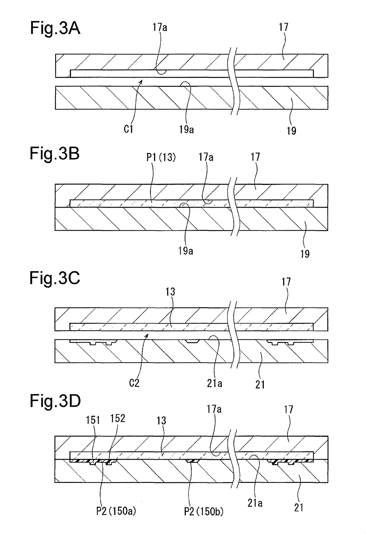
[0051]Parts of the rear surface 13b are respectively recessed toward the front surface 13a to form the first recess 131 and the second recesses 132. The first recess 131, which has the form of a frame, is recessed to surround the group of the opposing portions 130. The second recesses 132 are located at the inner side of the first recess 131 and are continuous with the upper side and lower side of the first recess 131. The second molding surface 19a of the second molding die 19 includes projections corresponding to the first recess 131 and the second recesses 132 to simultaneously form t...


PUM


Abstract

A solar panel includes a protection plate, a back cover, photovoltaic battery cells, a conductive member that electrically connects the photovoltaic battery cells to one another, and an encapsulant that is integrated with and located between the protection plate and the back cover. The encapsulant encapsulates the photovoltaic battery cells and the conductive member and fixes the photovoltaic battery cells and the conductive member to the protection plate and the back cover. The protection plate includes a resin transparent member, which is translucent from a front surface to a rear surface, and a resin opaque member, which is located at an outer side of each of the photovoltaic battery cells, shields the conductive member, and is arranged on the rear surface of the transparent member and integrated with the transparent member.

Description

BACKGROUND OF THE INVENTION[0001]The present invention relates to a solar panel.[0002]Japanese Laid-Open Utility Model Publication No. 6-39935 discloses a solar panel that includes a protection plate, a back cover, photovoltaic battery cells, a conductive member, and an encapsulant. The protection plate is formed from inorganic glass. The conductive member electrically connects the photovoltaic battery cells to one another. The photovoltaic battery cells and the conductive member are arranged between the protection plate and the back cover and encapsulated by the encapsulant. The encapsulated photovoltaic cells and conductive member are fixed to the protection plate and the back cover.[0003]In general, the conductive members of a solar panel are formed by metal plates and thus have a metallic color such as silver. Accordingly, when the solar panel is viewed from the front surface of a protection plate, the conductive members are more noticeable than necessary. This adversely affects...

Claims


Application Information

Patent Timeline
Patent Type & Authority Patents(United States)
IPC IPC(8): H01L31/049H01L31/048H01L31/05
CPCH01L31/049H01L31/05H01L31/048Y02E10/50
Inventor MITSUZAWA, HIDEYUKIOKUMURA, KAZUMASAINABA, HIROTAKA
Owner TOYOTA IND CORP
Why Eureka
Try Eureka