Louvre system

Inactive Publication Date: 2002-09-19
PIPIDOL
View PDF15 Cites 28 Cited by
  • Summary
  • Abstract
  • Description
  • Claims
  • Application Information

AI Technical Summary

Benefits of technology

0008] An advantage of the present invention is that by concealing the drive member within the frame the louvre blades can be better fitted within the louvre system frame as there is no requirement to accommodate the external drive arrangement as in previous systems. This not only improves the aesthetic appeal of the shuttering system but can substantially improve its performance as the blades can fit wholly within the frame thereby eliminating any gaps. Further, by incorporating the drive arrangement within the frame, the angle of movement of the blades can be much less restricted than these previous systems.
0009] In a preferred form, the drive arrangement incorporates coupling elements which are operative to be coupled to the individual louvre blades. The coupling elements are preferably in the form of drive shafts which project from the louvre blade into the frame and have the dual function of not only providing drive to the louvre blades but also to support the louvre blades correctly in position within the frame.
0010] In a preferred form, the drive arrangement further includes a plurality of gears which are associated with respective ones of the coupling elements, and at least one connecting element operative to transmit drive to the individual gears so as to provide the synchronised movement to the individual gears. The connecting element may be in the form of a flexible member such as belt, chain or rope, or a rigid member may be used such as a toothed rack, gear, camshaft or the like.
0011] For ease of manufacture, preferably each drive s

Problems solved by technology

In particular, as the bar is directly coupled to the louvre blades, the amount of movement of the blades is re

Method used


Image

  • Louvre system
  • Louvre system
  • Louvre system

Examples


Embodiment Construction

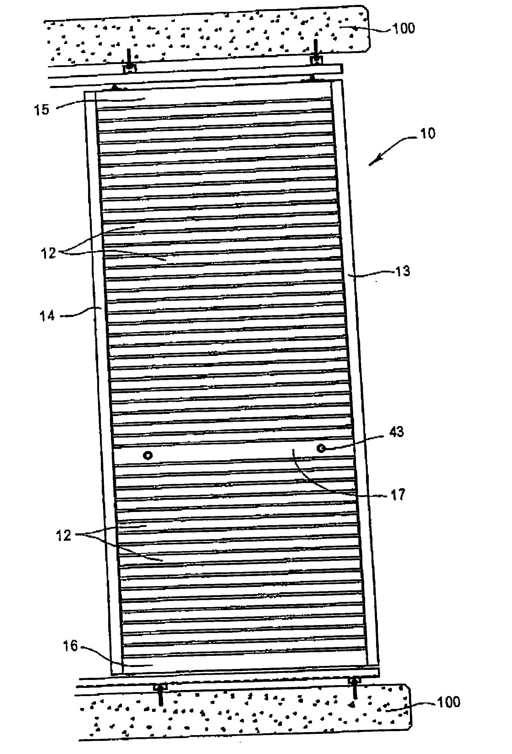
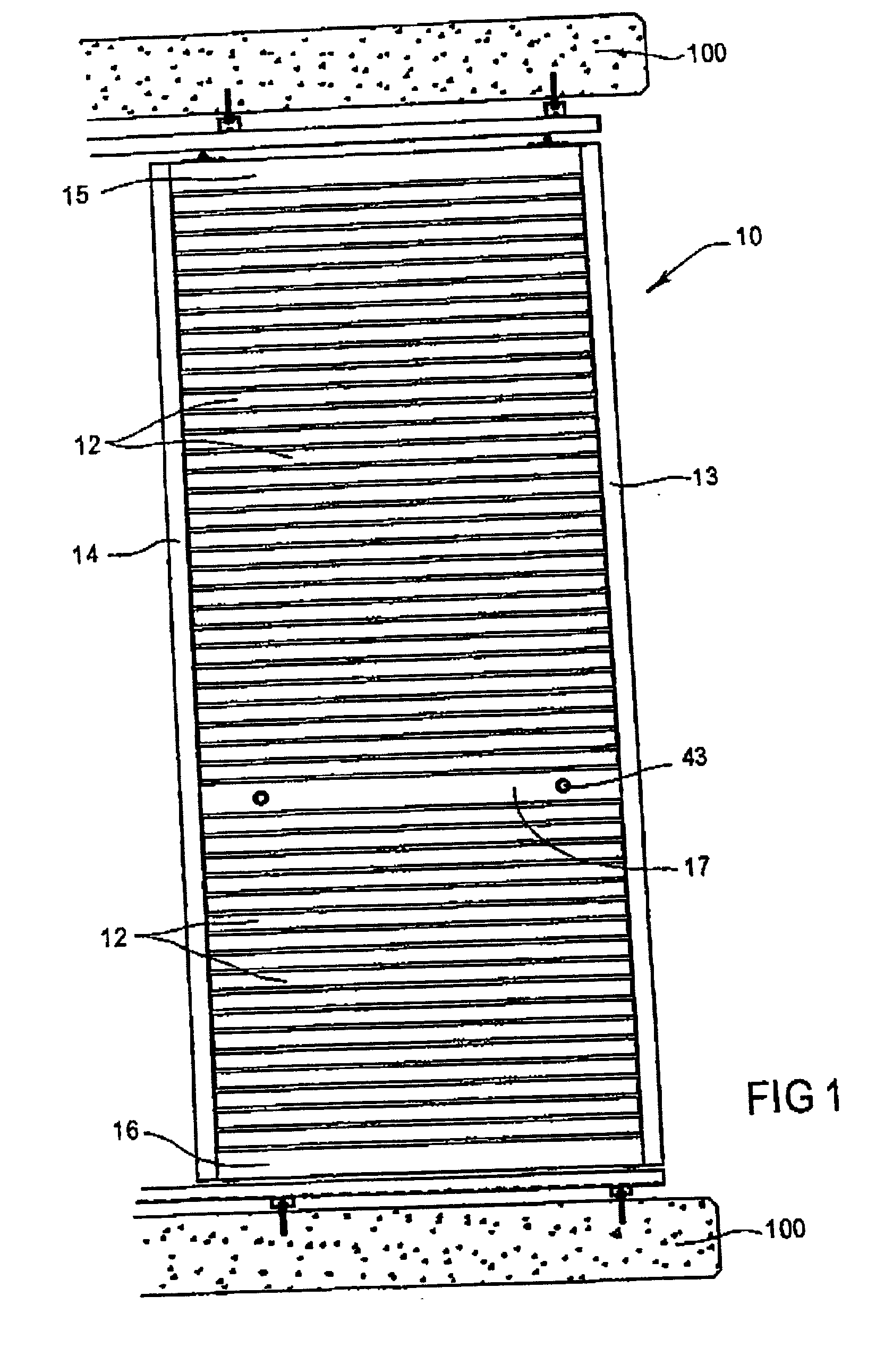
[0043] Turning firstly to FIGS. 1 and 2, a louvre shutter 10 is disclosed which includes a frame 11 and a plurality of louvre blades 12. The frame includes a pair of vertical side frame members 13, 14, which are interconnected by top and bottom frame members (15 and 16 respectively) and a transom 17.

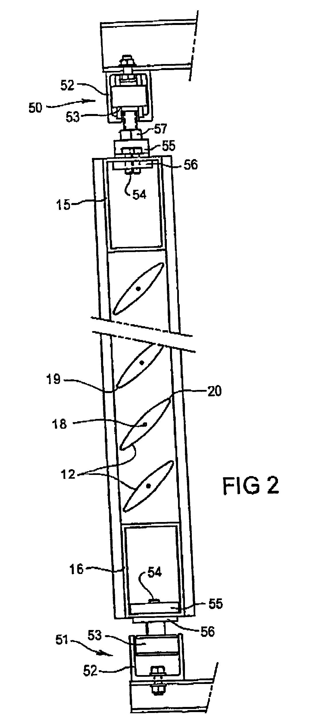
[0044] The blades 12 are elongate and have a cross sectional profile similar to that of an aerofoil (as best illustrated in FIG. 2). The blades 12 are mounted to the side frame members 13 and 14 so as to be pivotable about an axis of rotation 18. In this way, the blades are movable from a fully opened position where the leading and trailing edges (19 and 20) of the respective blades are generally horizontal so as to maximise the spacing between adjacent blades 12, to a fully closed position where adjacent blades are in abutting relationship with the leading edge 19 of one blade in contact with the trailing edge 20 of an adjacent blade.

[0045] In the illustrated arrangement, the shutter 10...


PUM


Abstract

A louvre system is disclosed which includes a frame having spaced apart side frame members (13, 14). A plurality of louvre blades are disposed between, and mounted to the side frame members (13, 14) so as to be rotatable about an axis of rotation. One of the frame members (14) includes a drive arrangement (21) which includes a plurality of gears (28) mounted on a subframe and connected to respective louvre blades. The gears are driven by a timing belt under the drive of a manual or electric actuator, to impart synchronised movement to the louvre blades.

Description

TECHNICAL FIELD[0001] The present invention relates to a louvre system. The invention has been designed especially, but not exclusively for use as a louvre shuttering for windows and doors and the like and the invention is herein described in that context. However, it is to be appreciated that the invention has broader application and may be used in other louvre arrangements.BACKGROUND[0002] Louvre shutters generally comprise an external frame in which a plurality of louvre blades are incorporated. These blades may be fixed to the frame but often are rotatable within the frame so as to be able to move into different orientations to vary the amount of space between adjacent blades. The advantage of louvre shuttering systems over solid shutters is that they can keep out direct sunlight or aid privacy while still allowing airflow through the shutter. The use of the rotatable louvre blades has a further advantage that the exact position of the louvre blades can be manually controlled so...

Claims


Application Information

Patent Timeline
IPC IPC(8): E06B7/084E06B7/086E06B7/088E06B7/09E06B7/096E06B9/28
CPCE06B7/086E06B9/28
Inventor METZEN, PAUL PETERUMLAUF, SIGFRIED
Owner PIPIDOL
Why Eureka
Try Eureka