Method of installing a spark containment cap

a technology of containment cap and installation method, which is applied in the direction of threaded fasteners, aircraft lighting protectors, fastening means, etc., can solve the problems of fuel leakage, negative pressure difference, and pressure drop within the cavity, so as to avoid sealing defects

Inactive Publication Date: 2019-02-26
AIRBUS OPERATIONS LTD
View PDF8 Cites 1 Cited by
  • Summary
  • Abstract
  • Description
  • Claims
  • Application Information

AI Technical Summary

Benefits of technology

[0008]The inventors have determined that an undesirable positive pressure difference, as described above, can be avoided by heating the trapped gas within the cavity to a temperature equal to or greater than the maximum expected ambient temperature (step (ii)) before installing the sealing material (step (iii)). The resulting drop in temperature of the trapped air within the cavity during cure of the sealing material (or at least during the early stages of cure, i.e. partial cure) will result in a pressure drop within the cavity, such that there is a negative pressure difference between the cavity and ambient (i.e. the pressure within the cavity is lower than the ambient pressure). Such a negative pressure difference can be tolerated, since it has been found to not result in the sealing material defects that a positive pressure difference can cause. In cases where the ambient temperature is equal to the maximum expected ambient temperature during installation and cure of the sealing material, there will be no pressure difference. Like a negative pressure difference, a lack of pressure difference also has the desirable effect of avoiding sealing defects.
[0011]In some embodiments step (i) includes providing a plurality of caps, each cap having a cap body terminating at a rim which surrounds an opening of a cavity for receiving the end of the fastener, step (iii) includes providing a bead of uncured sealing material around the rim of each cap body to seal the respective cavity, and in step (ii) the heated pad is placed in contact with each of the plurality of caps substantially simultaneously before steps (iii) and (iv) are carried out. In this way, multiple caps can be heated at once in order to reduce installation time.

Problems solved by technology

Such a positive pressure difference has been found to be undesirable because it can have the effect of causing defects within the bead of sealing material, such as air bubbles or voids, caused as the pressurised gas tries to escape from the cavity.
Such air bubbles are undesirable because they may compromise the quality of the seal around the cavity and thereby cause leakage of fuel through the fastener joint and / or may provide sites for uncontrolled sparking or out-gassing events.
The resulting drop in temperature of the trapped air within the cavity during cure of the sealing material (or at least during the early stages of cure, i.e. partial cure) will result in a pressure drop within the cavity, such that there is a negative pressure difference between the cavity and ambient (i.e. the pressure within the cavity is lower than the ambient pressure).

Method used


Image

  • Method of installing a spark containment cap
  • Method of installing a spark containment cap
  • Method of installing a spark containment cap

Examples


Embodiment Construction

)

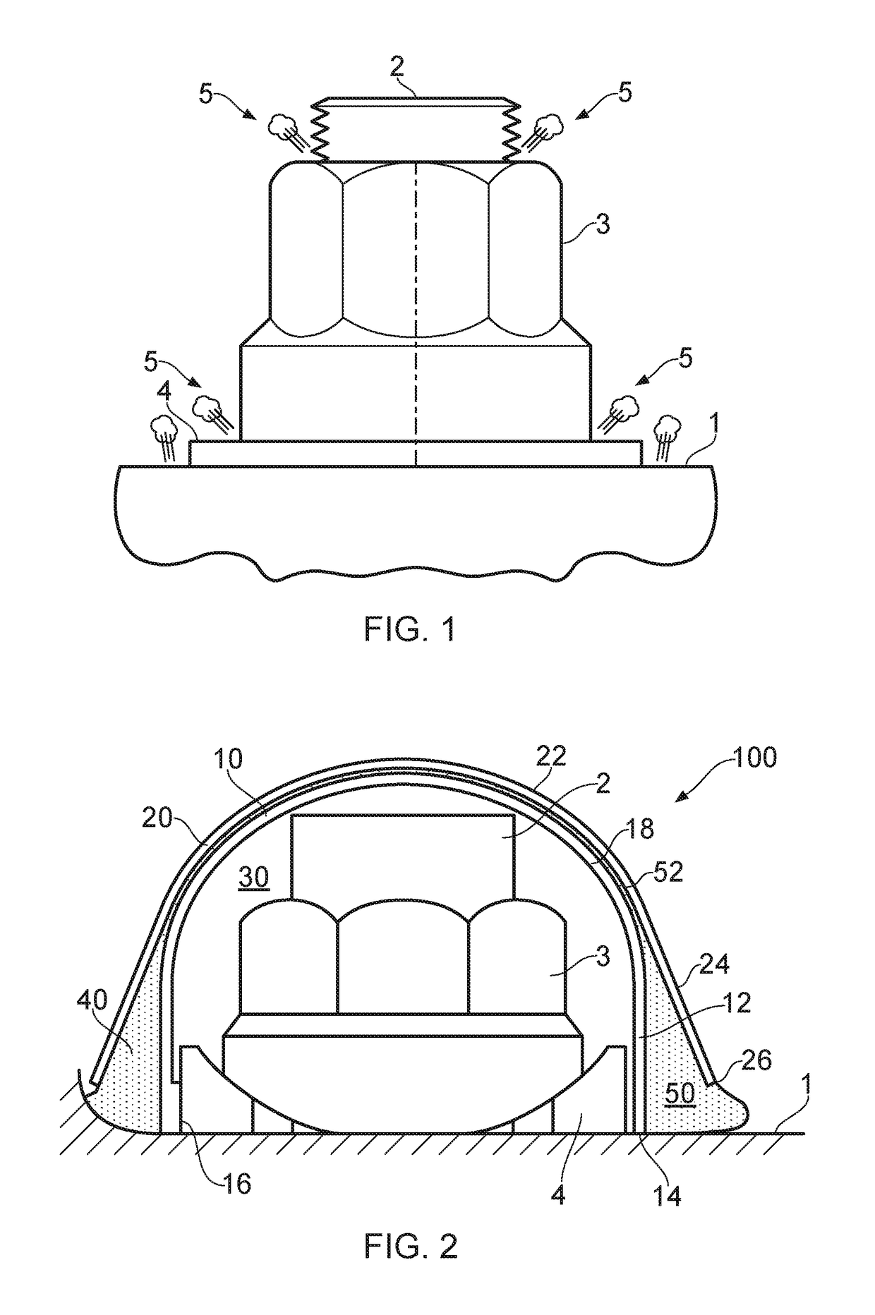
[0023]FIG. 2 illustrates a prior art spark containment cap 100 which can be used in a method according to an embodiment of the invention to form a sealed cavity 30 around the end of a fastener protruding from a structural member 1. In this embodiment the fastener end comprises the tail end of a bolt 2 in threaded engagement with a nut 2 seated on a spherical washer 4. In other embodiments the fastener end may comprise the head end of the bolt 2, or the fastener may comprise any other known fastener type, such as a rivet or swage fastener.

[0024]The cap 100 comprises an inner cap member 10 and an outer cap member 20 which is fitted snugly over the inner cap member 10. The inner and outer cap members 10, 20 are injection moulded from a thermoplastic material such as glass-filled polyetherimide (PEI). A suitable glass-filled PEI is Ultem™ 2400, which includes 40% glass fibres by volume. The inner and outer cap members may alternatively be made by moulding, by an additive manufacturing ...


PUM

PropertyMeasurementUnit
radiusaaaaaaaaaa
radiusaaaaaaaaaa
temperatureaaaaaaaaaa

Abstract

A method of forming a sealed cavity around an end of a fastener protruding from a structure is disclosed having the steps of: (i) installing a cap having a cap body terminating at a rim which surrounds an opening of a cavity over the end of the fastener so that the end of the fastener is enclosed within the cavity; (ii) heating the cap to increase a temperature within the cavity; (iii) providing a bead of uncured sealing material around the rim of the cap body to seal a volume of gas within the cavity; and (iv) curing the bead of sealing material during a cure period.

Description

RELATED APPLICATIONS[0001]The present application claims priority from Great Britain Application Number 1502133.0, filed Feb. 9, 2015, the disclosure of which is hereby incorporated by reference herein in its entirety.FIELD OF THE INVENTION[0002]The present invention relates to a method of forming a sealed cavity around an end of a fastener, and in particular to such a method comprising installing a spark containment cap over the fastener end.BACKGROUND OF THE INVENTION[0003]Large passenger aircraft are typically struck by lightning once or twice a year, each lightning bolt striking with up to 200,000 amps of electrical current that seeks the path of least electrical resistance. Many modern passenger aircraft have exterior surfaces made from composite materials which have a very high electrical resistance. There is therefore a high probability of lightening attachment at any of the many metallic fasteners in the exterior surface, which have a much lower electrical resistance. In the...

Claims


Application Information

Patent Timeline
Patent Type & Authority Patents(United States)
IPC IPC(8): F16B37/14B64D45/02F16B33/00
CPCF16B37/14F16B33/004B64D45/02Y10T29/49948
Inventor DOBBIN, RICHARDHUMPHRYS, BEN
Owner AIRBUS OPERATIONS LTD
Why Eureka
Try Eureka