Conductive member

a technology of conductive components and conductive wires, which is applied in the direction of connection insulation, single-bar/rod/wire/strip conductors, braided wire conductors, etc., can solve the problems of increasing the number of man-hours, increasing the manufacturing cost, and not being able to route the terminal end of tubular conductors to the device, so as to suppress the increase in manufacturing costs and prevent the entry of water

Inactive Publication Date: 2019-02-26
SUMITOMO WIRING SYST LTD
View PDF28 Cites 2 Cited by
  • Summary
  • Abstract
  • Description
  • Claims
  • Application Information

AI Technical Summary

Benefits of technology

[0005]Meanwhile, routing the wire harness in the above-described manner requires the use of an exterior member or the like, so that the number of components associated with the routing of the wire harness increases and also the number of the man-hours increases, resulting in an increase of the manufacturing costs.

Problems solved by technology

Meanwhile, routing the wire harness in the above-described manner requires the use of an exterior member or the like, so that the number of components associated with the routing of the wire harness increases and also the number of the man-hours increases, resulting in an increase of the manufacturing costs.
However, when the connection portion of a device is located behind another member, or the connection portion of a device is disposed in a narrow space, it is not possible to route the terminal end of the tubular conductor to the device.
However, the use of a tubular member having a larger inner diameter also increases the outer diameter dimension of the tubular member, thus resulting in an increase in the overall size of the conductive member.
The use of a tubular member having a small thickness dimension to solve this problem may prevent an increase in the size of the conductive member, but reduces the cross-sectional area of the tubular member, making it impossible to ensure a cross-sectional area sufficient to accommodate the amount of current passing through the core wire in the tubular member.

Method used


Image

  • Conductive member
  • Conductive member
  • Conductive member

Examples


embodiment 1

[0036]Embodiment 1 will be described with reference to FIGS. 1 to 4.

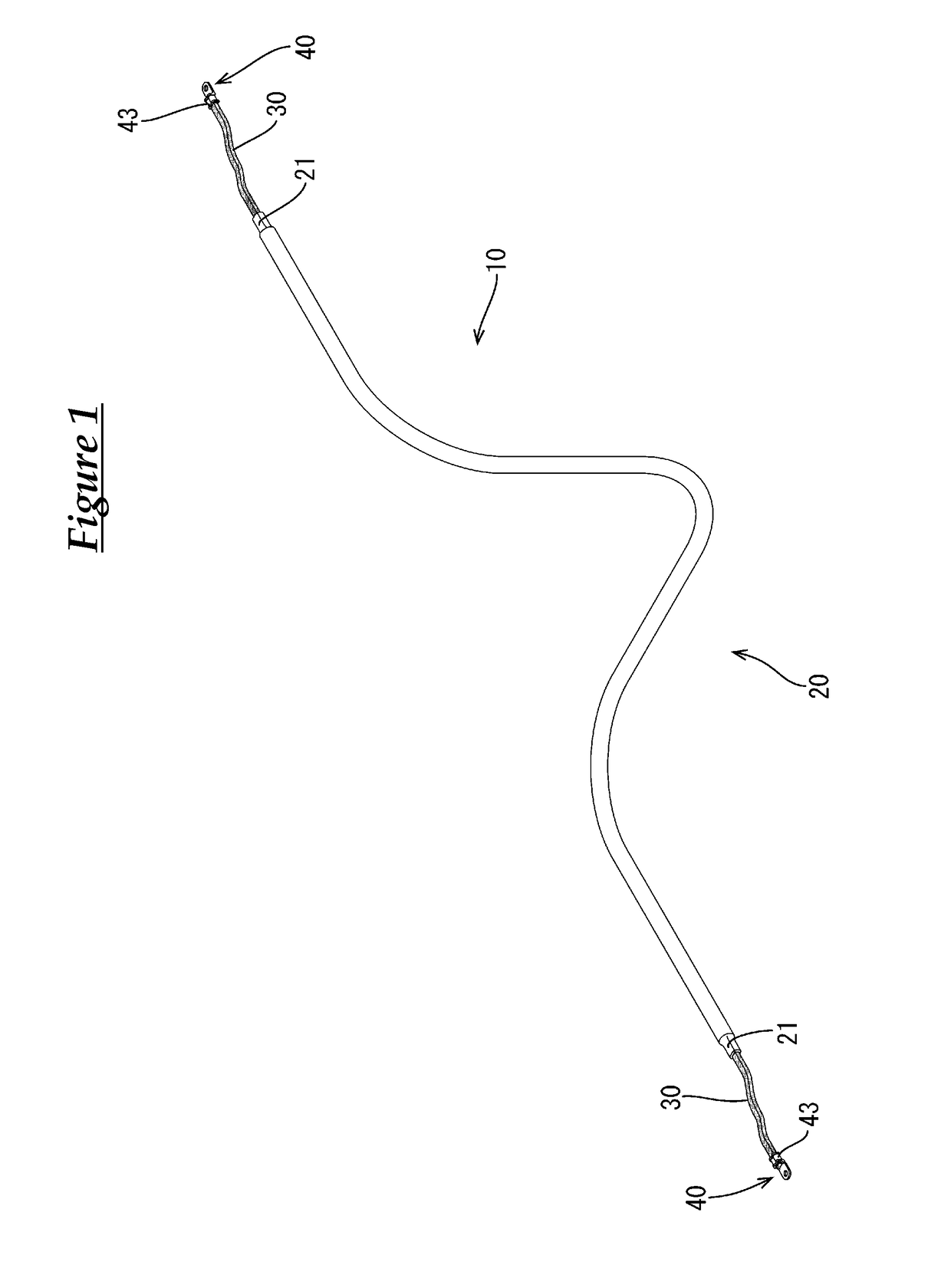
[0037]The present embodiment is directed at a signal-carrying conductive member 10 that connects a battery (not shown) disposed at the rear of a vehicle to devices (not shown) installed in an engine room provided at the front of the vehicle, and the routing path of the conductive member 10 between the battery and the engine room is underneath the floor of the vehicle.

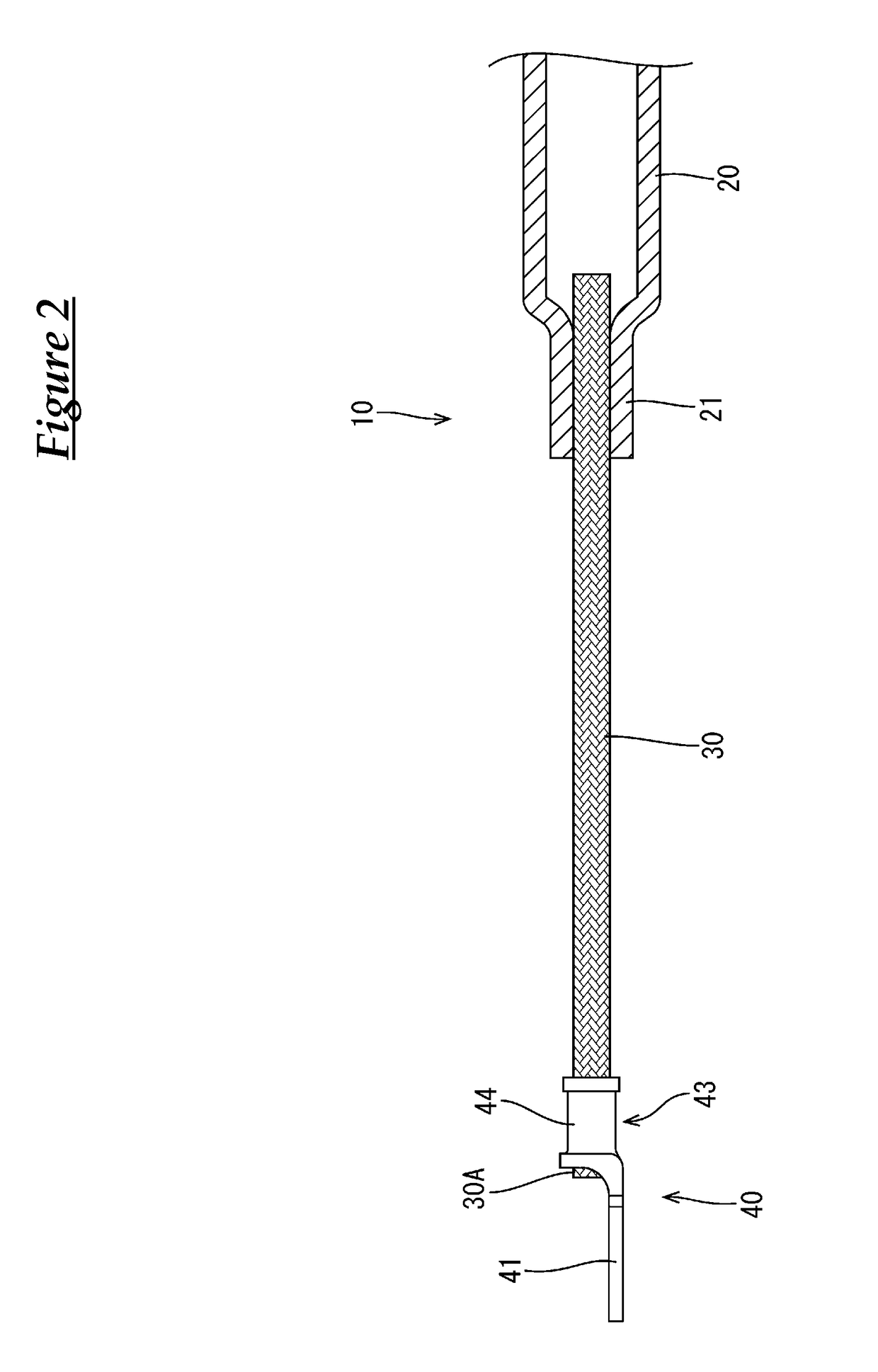
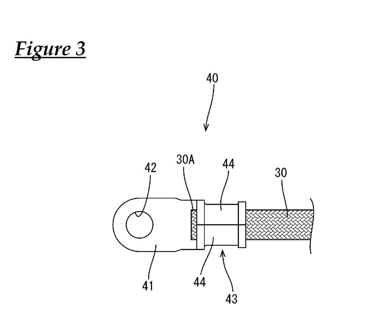
[0038]As shown in FIGS. 1 and 4, the conductive member 10 includes a pipe member (an example of a “tubular conductor”) 20 extending in the front-rear direction from the engine room to the rear of the vehicle underneath the floor of the vehicle, flexible braided wires (an example of a “flexible conductor”) 30 that are respectively connected to front and rear ends of the pipe member 20, round terminals (an example of a “terminal”) 40 that are connected to the respective braided wires 30 on the side opposite to the side where the pipe member 20 is connecte...

embodiment 2

[0066]Next, Embodiment 2 will be described with reference to FIG. 5.

[0067]A conductive member 110 according to Embodiment 2 is formed by changing the region covered by the heat-shrinkable tube 50 of Embodiment 1, and covering the end 30A of the braided wire 30 with solder (an example of a “sealant”) 60. The description of the components, function, and effect that are common to Embodiment 1 is redundant and therefore has been omitted. In addition, components that are the same as those of Embodiment 1 are denoted by the same reference numerals.

[0068]As shown in FIG. 5, the heat-shrinkable tube 150 of Embodiment 2 has a configuration in which the crimped portion 43 of the round terminal 40 is covered, up to approximately the central portion in the front-rear direction. That is, the heat-shrinkable tube 150 covers the entire perimeter of the region extending from approximately the central portion in the front-rear direction of the crimped portion 43 of the round terminal 40 disposed at ...

embodiment 3

[0071]Next, Embodiment 3 will be described with reference to FIG. 6.

[0072]A conductive member 210 according to Embodiment 3 is formed by changing the shape of the crimped connection portion 21 of Embodiment 1 and changing the braided wire 30 to a coated wire 230. The description of the components, function, and effect that are common to Embodiment 1 is redundant and therefore has been omitted. In addition, components that are the same as those of Embodiment 1 are denoted by the same reference numerals.

[0073]As shown in FIG. 6, the coated wire 230 of Embodiment 3 is formed by covering a core wire 231 made of a plurality of bare metal strands having excellent conductivity with an insulating coating 232. At a terminal end of the coated wire 230, the insulating coating 232 is stripped off to expose the core wire 231, and the exposed core wire 231 is connected to the crimped portion 43 of the round terminal 40 and a crimped connection portion 231 of a pipe member 20, which will be descri...


PUM

PropertyMeasurementUnit
conductiveaaaaaaaaaa
conductivityaaaaaaaaaa
shape retainabilityaaaaaaaaaa

Abstract

A conductive member disclosed herein is a conductive member that is routed from the front to the rear of a vehicle, and includes: a shape-retaining tubular pipe member made of a metal having excellent conductivity; a braided wire having flexibility and configured to be crimped to be connected to a crimped connection portion provided at front and rear ends of the pipe member; a round terminal configured to be crimped and connected to the braided wire; and a heat-shrinkable tube that covers from a crimped portion of the round terminal at the front end to a crimped portion of the round terminal at the rear end.

Description

CROSS REFERENCE TO RELATED APPLICATIONS[0001]This application claims the priority of Japanese patent application JP2015-086441 filed on Apr. 21, 2015, the entire contents of which are incorporated herein.TECHNICAL FIELD[0002]The technique disclosed herein relates to a conductive member.BACKGROUND ART[0003]A wire harness as described for example in JP 2012-130185A (referred to as “Patent Document 1”) is known as a wire harness that connects devices and a battery installed in a vehicle. Terminals are provided respectively at opposite ends of the wire harness, and the terminals are connected to connection portions of the devices and a connection portion of the battery, respectively, and thereby, the devices are connected to each other by the wire harness.[0004]When routing the wire harness, for example, underneath the floor of the vehicle, it is necessary to hold the wire harness along a routing path, while preventing the wire harness from drooping. Accordingly, the wire harness is rou...

Claims


Application Information

Patent Timeline
Patent Type & Authority Patents(United States)
IPC IPC(8): H01B5/06H01R11/12H01R4/18H01B5/12H01R4/72H01R4/02
CPCH01B5/12H01B5/06H01R4/023H01R11/12H01R4/184H01R4/72H01R4/183H01B5/02
Inventor KUSHIMA, TAKAONAKAI, HIROKAZU
Owner SUMITOMO WIRING SYST LTD
Why Eureka
Try Eureka