Cervical brace

a cervical brace and head support technology, applied in the field of cervical braces, can solve the problems of neck sprain or neck strain, paralysis or death, braces and collars, etc., and achieve the effect of enhancing the user experience and enhancing the comfort of users

Inactive Publication Date: 2019-03-12
CERVICAL CHINUP
View PDF16 Cites 0 Cited by
  • Summary
  • Abstract
  • Description
  • Claims
  • Application Information

AI Technical Summary

Benefits of technology

[0026]The two struts may be adapted to be disposed angularly with respect to each other, whereby in use the two struts can extend upwardly and inwardly towards the mandible of the user. This arrangement is advantageous as it facilitates support for, and positioning of, the two rest members in a manner which does not adversely obstruct the field of vision of the user. In particular, the arrangement facilitates support for, and positioning of, the two rest members in a manner which is less intrusive and more aesthetically pleasing than current neck supporting devices. Furthermore, it is believed that the arrangement is neither too bulky nor cumbersome aesthetically as to constitute a deterrent to use of the support apparatus.
[0030]The capacity to selectively vary the length of the struts, the position of the struts with respect to the base portion (including variation of the position at which each strut is attached to the base portion and also the angular disposition of each strut with respect to the base portion), and the orientation of the rest members with respect to the struts provides the adjustability to accommodate characteristics of the user.
[0038]The struts may be mounted on the two limb portions of the yoke structure. In particular, each strut may be adjustably mounted on a respective one of the two limb portions. The adjustable mounting of each strut on the respective limb portion of the yoke structure may allow selective displacement of the strut along the limb portion for varying the position at which the strut is attached to the limb portion. Additionally, the adjustable mounting of each strut on the respective limb portion of the yoke structure may allow angular movement of the strut about the limb portion for varying the angular disposition of the strut. With this arrangement, each limb portion may provide a rail around which the strut is selectively moveable angularly and / or along which the strut is selectively slidable.
[0049]The neck support apparatus may incorporate cushioning for comfort of the user when fitted with the neck support apparatus. In particular, various parts of the base portion and / or the support portion may be padded, encased, or otherwise fitted with cushioning material to enhance the comfort of the user. By way of example, the yoke structure may be provided with cushioning on the bridge portion where it is contacting the back of the neck and the front end of the limb portions where they will be contacting the collar bones / clavicles.
[0050]The neck support apparatus may also be equipped with ancillary devices and apparatus for various purposes, including enhancing the user experience. By way of example, the neck support apparatus may be equipped with headphone system and / or a microphone.
[0052]The support apparatus may be operable to support for the head of the user by resisting forward tilting of the head of the user beyond a predetermined point, to thereby afford support for the neck of the user. With this arrangement, the support apparatus can afford posture support to a user.

Problems solved by technology

Minor injuries to the neck tend to be based upon stress sustained to the soft tissue, leading to a neck sprain or neck strain.
Major injuries to the neck tend to involve direct damage to the cervical spine, such as fractures, which can lead to loss of feeling, paralysis or death.
Both neck braces and collars have the disadvantage of not allowing patients who have minor soft tissue injury or who have recently recovered from major cervical vertebrae and / or soft tissue injury to engage in active exercise, which may be beneficial during the physical therapy phase of treatment.
Furthermore, known neck braces and collars typically have further disadvantages of not being cosmetically pleasing, and also being invasive and uncomfortable to wear.
Consequently, patients might not wear the neck braces and collars as prescribed, which may contribute to their ineffectiveness in treating neck injury in some cases.

Method used


Image

  • Cervical brace
  • Cervical brace
  • Cervical brace

Examples


first embodiment

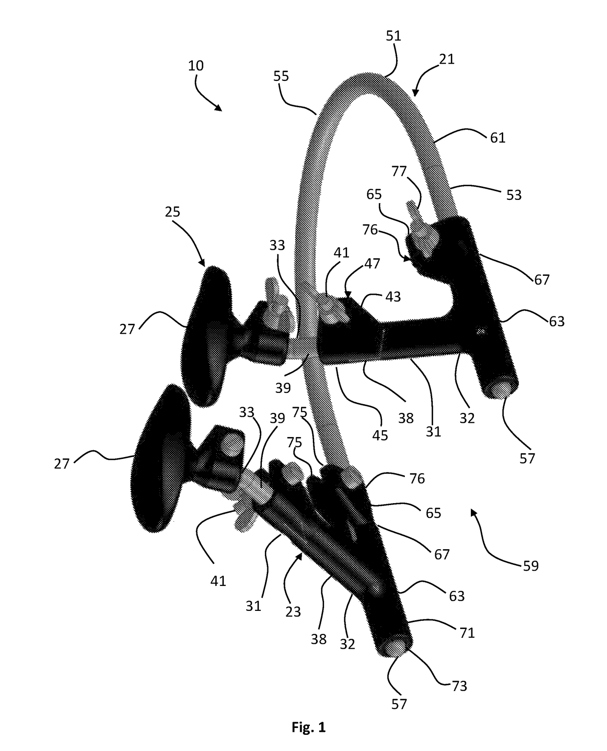
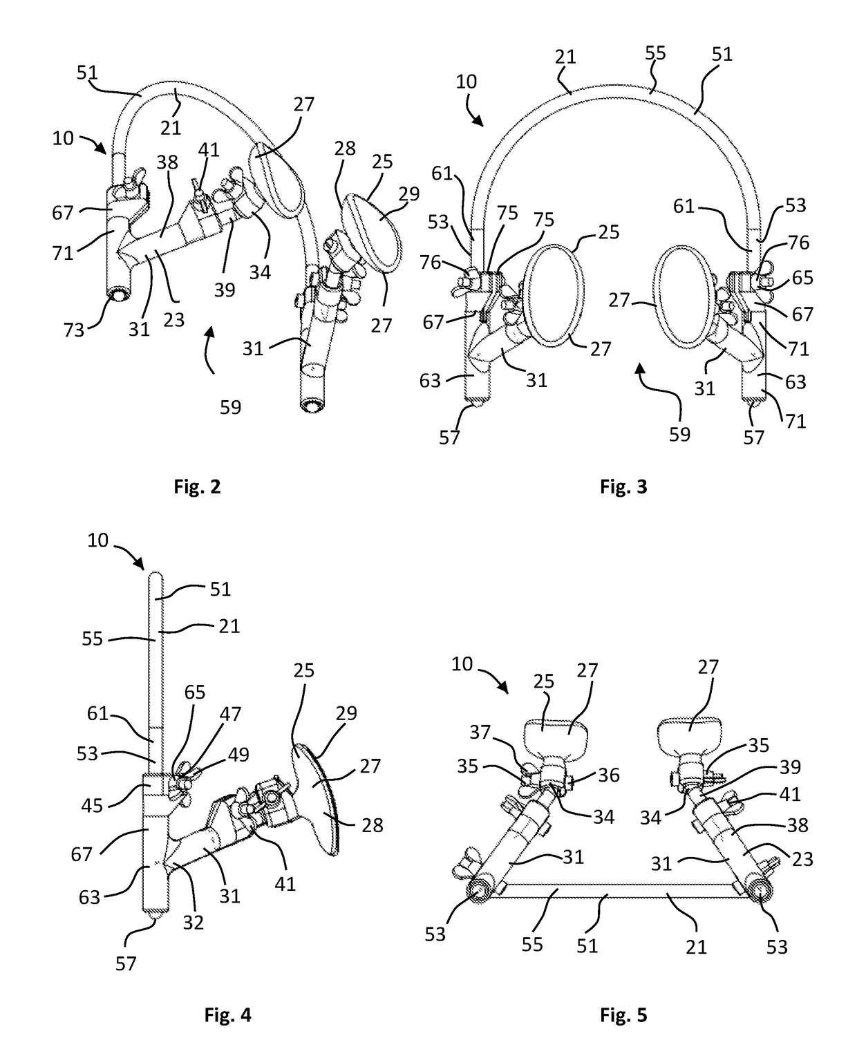
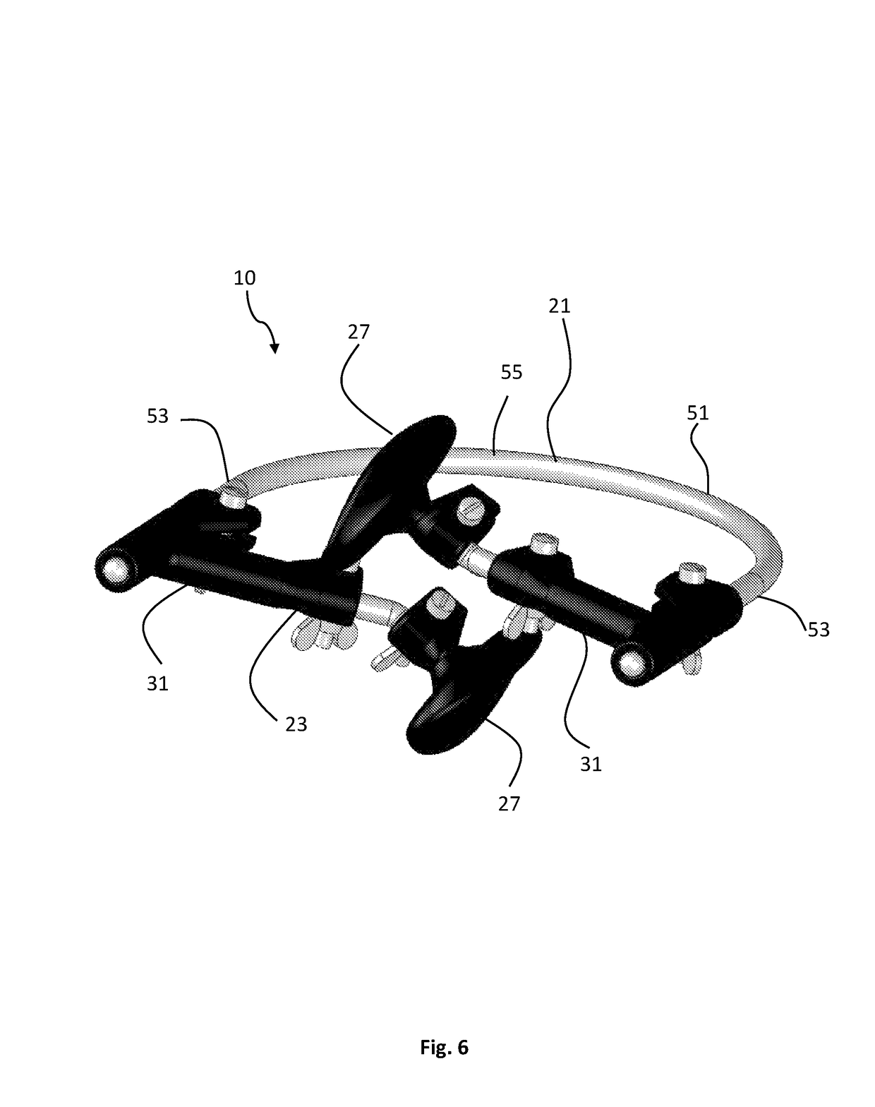
[0088]Referring to FIGS. 1 to 12, there is shown a neck support apparatus 10 according to the invention. The neck support apparatus 10 is described and illustrated in some drawings as being fitted onto a user 11. The user 11 is depicted with various anatomical features; namely, head 13, neck 14, shoulders 15, chin 16, mandible 17, upper torso 18 and chest 19.

[0089]When so fitted, the neck support apparatus 10 allows freedom of movement of the head 13 of the user 11, other than limiting forward flexion by resisting forward tilting of the head beyond a predetermined point as illustrated in FIGS. 8 and 9. The neck support apparatus 10 allows the user to assume a normal upright condition, as illustrated in FIG. 7. In the forwardmost tilted position of the head 13 of the user 11, the head of the user rests on the apparatus 10 and the apparatus 10 thereby affords support for the neck 14 of the user. More particularly, the mandible 17 of the user 11 rests on the apparatus 10. In other word...

second embodiment

[0121]In this second embodiment, each strut 31 is constructed to yieldingly deform in the axial direction when subjected to a loading imposed upon it through the mandible 17 of the user during forwarding tilting of the head 13 user beyond said predetermined point.

[0122]In the arrangement shown, the outer strut section 39 of each strut 31 comprises an extensible member 80 which is resiliently contactable under inward axial loading. Specifically, the extensible member 80 comprises first and second sections 81, 82 interconnected in axial sliding relation to provide a telescoping arrangement. The extensible member 80 further comprises biasing means 83 such as a compression spring operating between the first and second sections 81, 82 to urge them apart so that the extensible member 80 assumes a fully extended condition. The extensible member 80 is contractible in response to inward axial loading exceeding the opposing force exerted by the biasing means 83, with the biasing means 83 yiel...

fourth embodiment

[0129]the neck support apparatus 10 is configured as a base portion 21, wearable on a user's upper torso 18, and an integrally mounted support portion 23, adapted to engage and support the user's chin 16 and thereby offer neck support.

[0130]The base portion 21 and the support portion 23 of the neck support apparatus 10 are of integral construction and comprise a plastics material.

[0131]The base portion 21 comprises a chest plate 101 which is in contact with a user's chest 19, and a shoulder support 103 configured as two hooked members 105 and 107 which are integrally connected to the chest plate 101. The hooked members 105 and 106 extend above the front, around the top and down the back of a user's shoulders 15, to anchor the neck support apparatus 10 to the upper torso 18.

[0132]The support portion 23 comprises a projection 111 which is integrally attached to the base portion 21 on the upper front section of one of the hooked members 105 or 107. The projection 111 is configured as a...


PUM


Abstract

A neck support apparatus (10) has a base portion (21) for positioning on the torso (18) of the user (11) and a support portion (23) extending from the base portion and having a rest (25) upon which the mandible (17)) of the user (11) can rest when the head (13) of the user is at the forwardmost tilted position. The rest (25) has two rest members (27) configured to receive the mandible (17), typically adjacent the underside of the posterior mandibles (17a) of the user (11). The support portion (23) further comprises two struts (31) which are mounted on the base portion (21) and on which the rest members (27) are mounted. The two struts (31) are adapted to be disposed angularly with respect to each other.

Description

TECHNICAL FIELD[0001]The present invention relates to an apparatus for supporting the head of a user.[0002]More particularly, the invention is concerned with apparatus operable to resist forward tilting of the head of the user beyond a predetermined point to thereby afford support for the neck of the user.[0003]The invention has been devised particularly, although not necessarily solely, in relation to provision of posture support for a use. The apparatus may function as a neck brace which are also known as cervical braceBACKGROUND ART[0004]The following discussion of the background art is intended to facilitate an understanding of the present invention only. The discussion is not an acknowledgement or admission that any of the material referred to is or was part of the common general knowledge as at the priority date of the application.[0005]The human neck comprises of seven cervical vertebrae (bones) known in its entirety as the cervical spine. The cervical vertebrae form the uppe...

Claims


Application Information

Patent Timeline
Patent Type & Authority Patents(United States)
IPC IPC(8): A61F5/055A61F5/058A63B23/025A63B21/02A63B21/04A63B21/00A63B71/06
CPCA61F5/055A61F5/05883A63B21/026A63B21/0442A63B21/4005A63B23/025A63B21/4025A63B2220/17A61F2250/0004A63B71/0622A63B2210/50
Inventor HARDCASTLE, PHILIP HOBSONOLDAKOWSKI, MATTHEW PETEROLDAKOWSKA, INTAN CAMELLIA WATONOLIEW, BRANDON JIN SIEW
Owner CERVICAL CHINUP
Why Eureka
Try Eureka