
Catheter assembly

a catheter and assembly technology, applied in the direction of catheters, guide needles, etc., can solve the problems of user difficulty in puncturing, and achieve the effect of smooth separation of catheters and smooth operation

Active Publication Date: 2019-03-26
TERUMO KK
View PDF6 Cites 4 Cited by
  • Summary
  • Abstract
  • Description
  • Claims
  • Application Information

AI Technical Summary

Benefits of technology

[0008]Certain embodiments of the present invention can help to solve the above-described problem and are directed to providing a catheter assembly in which a catheter and an inner needle can be prevented from being warped along with puncture while mobility of the catheter is secured, and a user can smoothly perform operation without feeling any discomfort.
[0039]According to certain embodiments of the present invention, the catheter assembly can prevent the catheter and the inner needle from being warped along with puncture while securing mobility of the catheter, and the user can smoothly perform operation without feeling any discomfort.

Problems solved by technology

However, in the case where such a space exists, the catheter or the inner needle may be warped inside the needle hub by reaction force received from a patient at the time of puncturing the patient with the long catheter and an inner needle, and a user may feel difficulty in puncturing.

Method used


Image

  • Catheter assembly
  • Catheter assembly
  • Catheter assembly

Examples


first embodiment

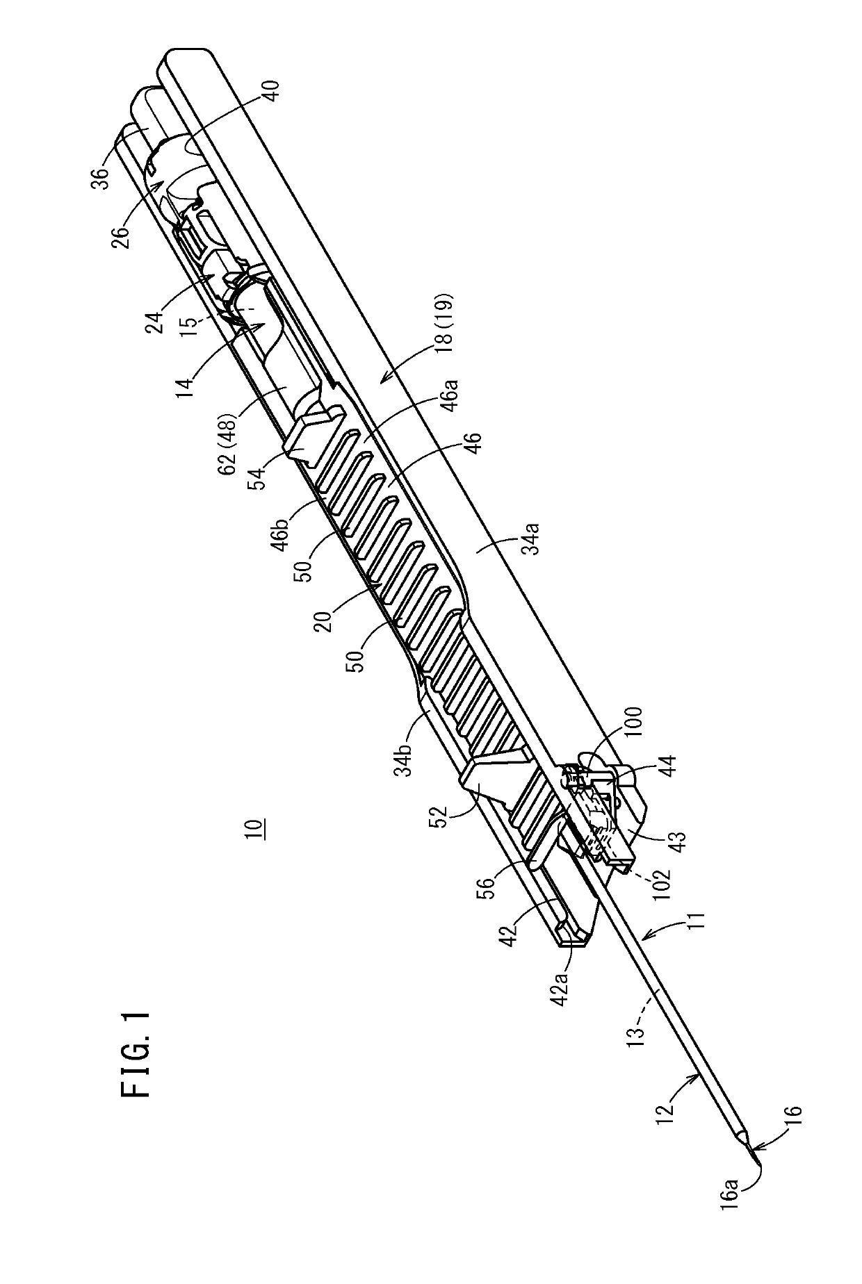
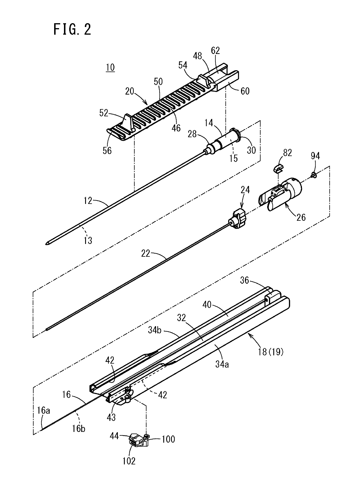
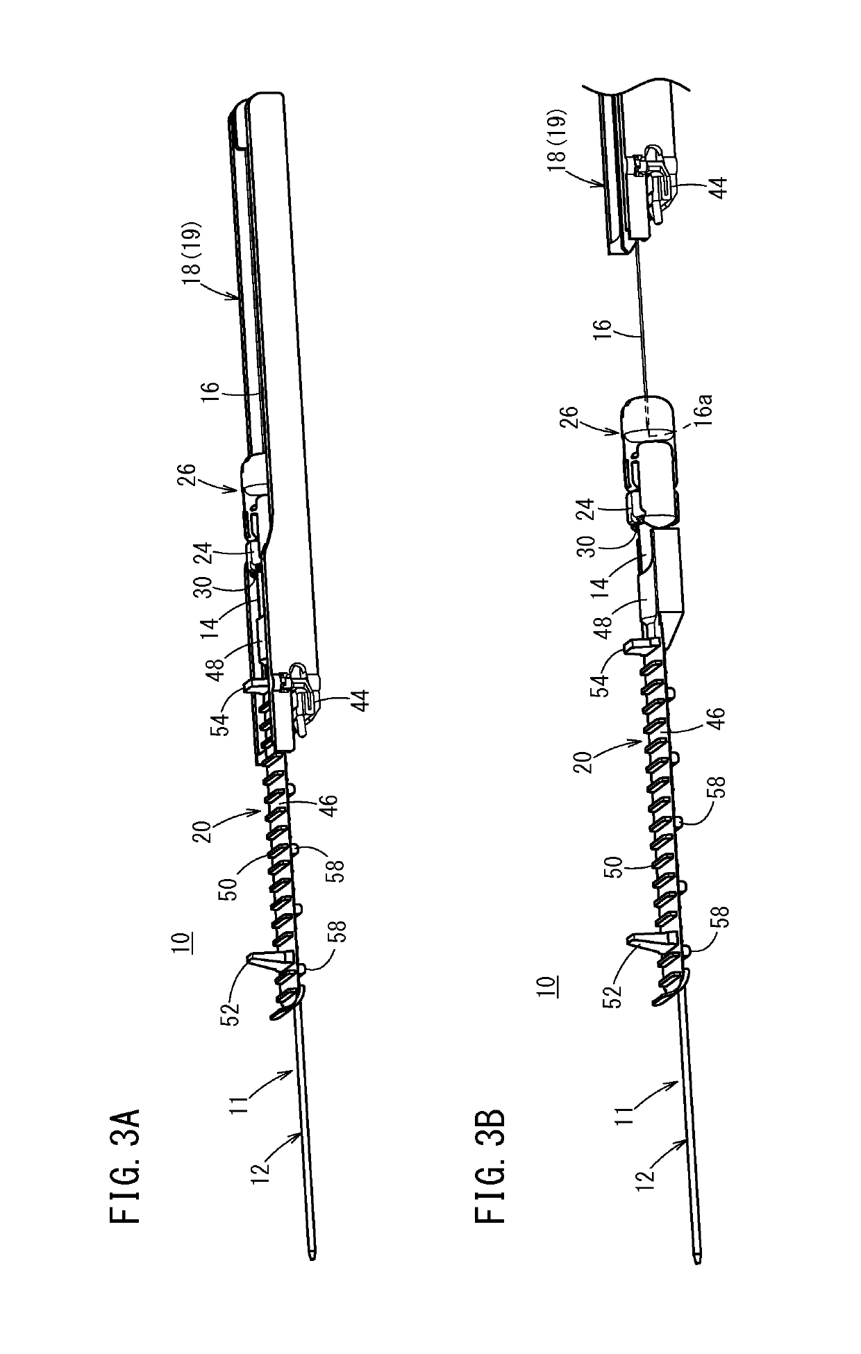
[0055]As illustrated inFIGS. 1 and 2, a catheter assembly 10 according to a first embodiment includes a catheter 12, a catheter hub 14 to fix and hold the catheter 12, a hollow inner needle 16 inserted into the catheter 12, a needle hub 18 to fix and hold the inner needle 16, a catheter operation member 20 attached to an upper side of the catheter hub 14, a tube-like auxiliary member 22 inserted between the catheter 12 and the inner needle 16, an auxiliary member hub 24 to fix and hold the auxiliary member 22, and a needle protection member 26 connected to the catheter hub 14 and a proximal end of the auxiliary member hub 24.

[0056]In an initial state before use, the catheter assembly 10 has a multiple tube structure (multiple tube unit 11) in which the catheter 12, auxiliary member 22, and inner needle 16 are stacked sequentially from the outside. The catheter operation member 20 has a structure to directly hold the multiple tube unit 11. Additionally, in the initial state, the cath...

second embodiment

[0110]Next, a catheter assembly 200 according to a second embodiment of the present invention will be described. Note that a reference sign same as the one used in a first embodiment has the same structure or the same function in the embodiment described below, and a detailed description therefor will be omitted.

[0111]The catheter assembly 200 according to the second embodiment differs from a catheter assembly 10 according to the first embodiment in that a catheter operation member 202 is bent in an initial state in which the catheter operation member 202 is housed in a needle hub 204 as illustrated in FIG. 9. Furthermore, the catheter assembly 200 has a structure in which a support member 44 in FIG. 1 is not provided and a catheter 12 (multiple tube unit 11) is held and supported only by the catheter operation member 202.

[0112]As illustrated in FIGS. 10A and 10B, because the needle hub 204 houses a whole portion of side edges 202a, 202b of the catheter operation member 202 in the h...


PUM


Abstract

A catheter assembly includes a hollow catheter; a catheter hub configured to fix and hold the catheter; an inner needle including a needle tip and configured to be removably inserted through an inside of the catheter; a needle hub configured to fix and hold the inner needle; and a catheter operation member capable of moving the catheter relative to the inner needle. The catheter operation member includes a holding portion configured to directly hold the catheter in a detachable manner.

Description

CROSS-REFERENCE TO RELATED APPLICATIONS[0001]The present application is a continuation of PCT Application No. PCT / JP2016 / 063913, filed on May 10, 2016, which claims priority to Japanese Patent Application No. 2015-100353, filed on May 15, 2015, both of which are hereby incorporated by reference in their entireties.BACKGROUND[0002]Technical Field[0003]The present disclosure relates to a catheter assembly adapted to puncture a blood vessel and be indwelled while performing infusion to a patient, for example.[0004]Background Art[0005]In the related art, a catheter assembly is used while performing infusion to a patient. This kind of the catheter assembly includes a hollow catheter, a catheter hub fixed to a proximal end of the catheter, a hollow inner needle inserted into the catheter and having a sharp needle tip at a distal end, and a needle hub fixed to a proximal end of the inner needle (refer to JP 2013-529111 A).[0006]Furthermore, in the catheter assembly disclosed in JP 2013-529...

Claims


Application Information

Patent Timeline
Patent Type & Authority Patents(United States)
IPC IPC(8): A61M25/06A61M25/00A61M25/01
CPCA61M25/0606A61M25/0017A61M25/0668A61M25/0618A61M25/0113
Inventor ISHIDA, MASAHIRO
Owner TERUMO KK
Learn More