Fastening-type pipe supporting apparatus for curved pipe

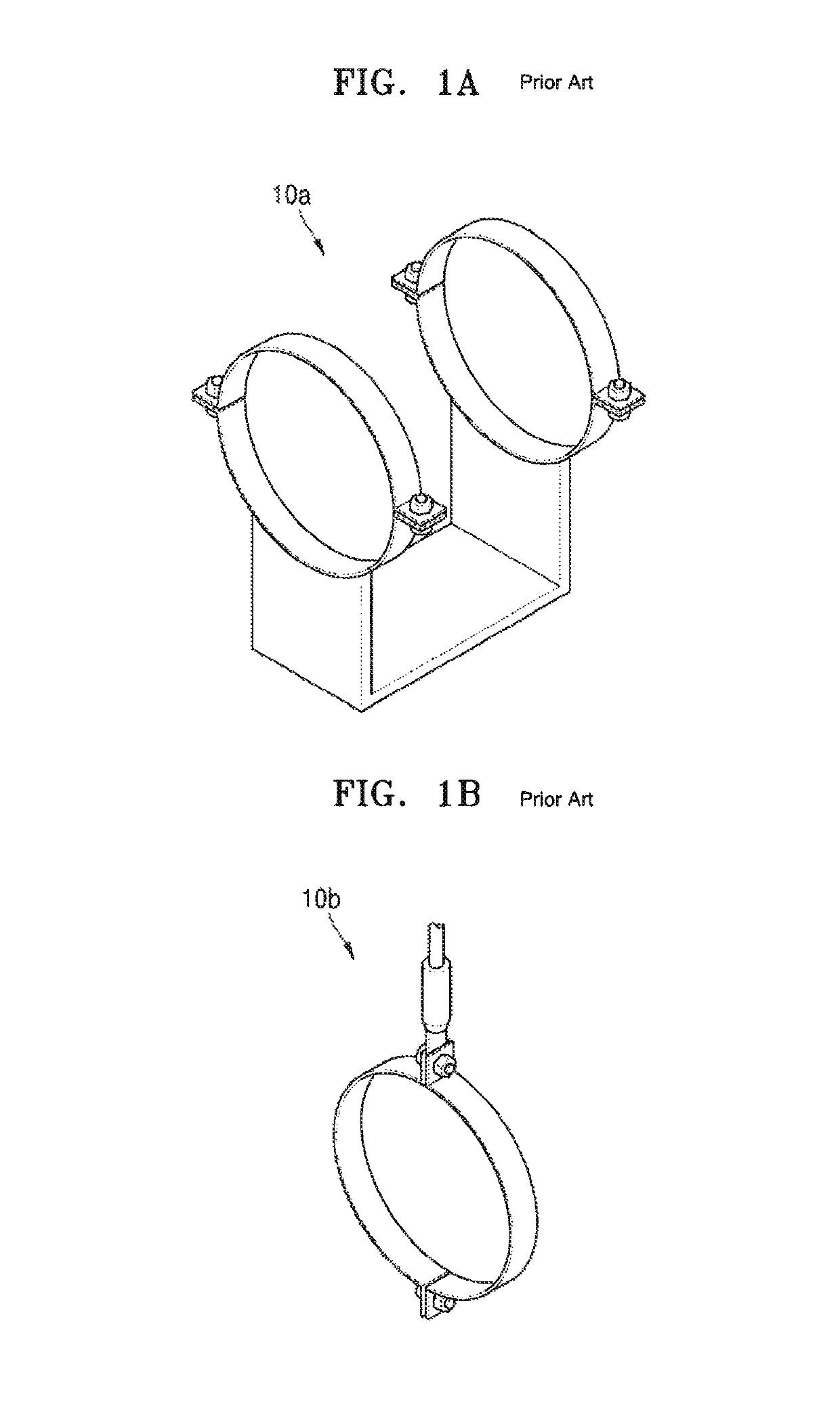
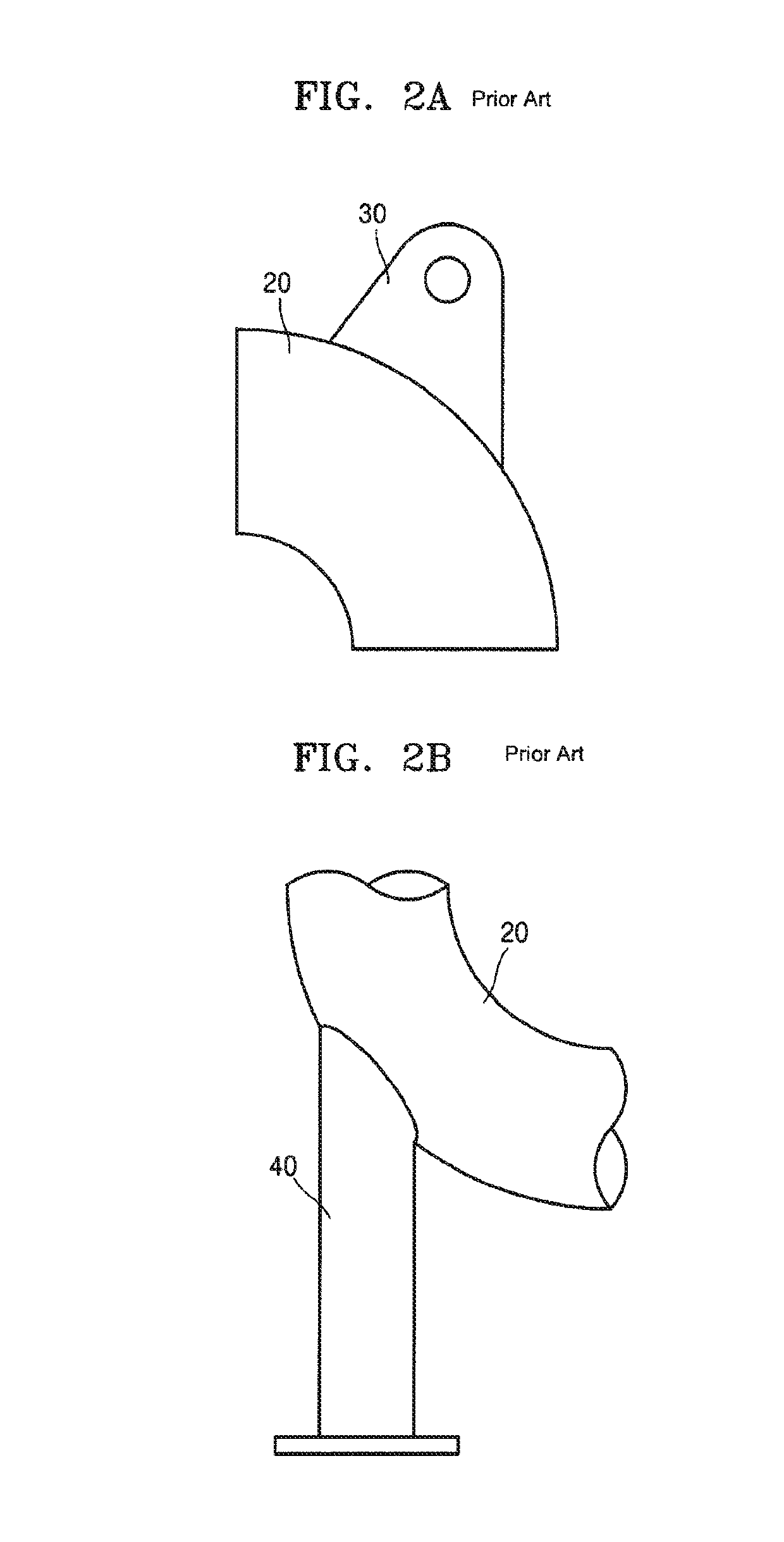
a technology of supporting apparatus and curved pipes, which is applied in the direction of fastening means, bends, washers, etc., can solve the problems of inability to measure the thickness of the curved portion of the pipe, the attachment part is not separable from the pipe, and the attachment-type has a negative effect on the structural integrity of the pipe, so as to achieve the effect of convenient attachmen

Active Publication Date: 2019-03-26
KEPCO ENG & CONSTR CO INC
View PDF50 Cites 9 Cited by
  • Summary
  • Abstract
  • Description
  • Claims
  • Application Information

AI Technical Summary

Problems solved by technology

For example, in the case of the attachment-type, an attachment part is directly welded to a pipe, and thus, the attachment part is not separable from the pipe.
Thus, when it is required to measure the thickness of a curved portion of a pipe so as to verify the amount of internal corrosion of the pipe, the attachment part welded to the curved portion of the pipe makes it impossible to measure the thickness of the curved portion of the pipe.
In addition, the attachment-type has a negative effect on the structural integrity of pipes and requires an additional local stress evaluation because of parts welded to pipes.
However, the development of fastening-type pipe supporting apparatuses for curved portions of pipes is not yet sufficient, and thus only attachment-type pipe supporting structures are used for curved portions of pipes.
As described above, however, such an attachment-type pipe supporting structure is practically not separable from a pipe after the attachment-type pipe supporting structure is welded to the pipe, and thus, it is practically impossible to measure the thickness of the curved portion of the pipe for verifying internal corrosion at the curved portion of the pipe.
In addition, such attachment-type pipe supporting structures have a negative effect on the structural integrity of pipes, and even more, an additional local stress evaluation is required because of parts welded to pipes.
However, if pipe supporting structures or apparatuses are installed on only straight portions of pipes as described above, it is difficult to select optimal positions for supporting loads.
That is, because of limitations of the pipe supporting structures or apparatuses for curved portions of pipes, it is difficult to select optimal installation positions for pipe supporting structures or apparatuses.

Method used


Image

  • Fastening-type pipe supporting apparatus for curved pipe
  • Fastening-type pipe supporting apparatus for curved pipe
  • Fastening-type pipe supporting apparatus for curved pipe

Examples


Embodiment Construction

[0031]Reference will now be made in detail to embodiments, examples of which are illustrated in the accompanying drawings, wherein like reference numerals refer to like elements throughout. In this regard, the present example embodiments may have different forms and should not be construed as being limited to the descriptions set forth herein. Accordingly, the example embodiments are merely described below, by referring to the figures, to explain aspects of the present description. As used herein, the term “and / or” includes any and all combinations of one or more of the associated listed items. Expressions such as “at least one of,” when preceding a list of elements, modify the entire list of elements and do not modify the individual elements of the list.

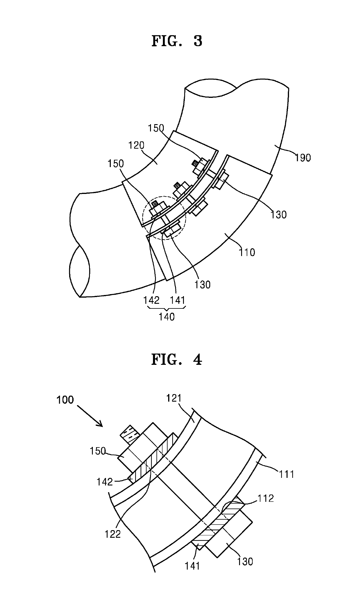
[0032]Example embodiments relate to a fastening-type pipe supporting apparatus configured to support a curved pipe against loads acting on the curved portion of the pipe using clamps having curved surfaces and to be easily attached ...


PUM


Abstract

A fastening-type pipe supporting apparatus capable of supporting a curved pipe against loads acting on a curved portion of the pipe via clamps having curved surfaces and being easily attached to and detached from the curved portion of the pipe. The fastening-type pipe supporting apparatus includes: a first clamp having a semicircular cross-sectional shape and a curved surface with a curvature to surround the curved portion of a pipe; a second clamp having a semicircular cross-sectional shape and a curved surface with a curvature to surround the curved portion of the pipe, the second clamp being coupled to the first clamp; a connection bolt coupling the first clamp with the second clamp; and a washer placed around the connection bolt.

Description

CROSS-REFERENCE TO RELATED APPLICATION[0001]This application claims the benefit of Korean Patent Application No. 10-2015-0190809, filed on Dec. 31, 2015, in the Korean Intellectual Property Office, the disclosure of which is incorporated herein in its entirety by reference.BACKGROUND[0002]1. Field[0003]One or more example embodiments relate to an apparatus for supporting a curved portion of a pipe, more particularly, to a fastening-type pipe supporting apparatus capable of supporting a curved pipe against loads acting on the curved portion of the pipe via clamps having curved surfaces and being easily attached to and detached from the curved portion of the pipe.[0004]2. Description of the Related Art[0005]In general, pipes having various shapes are used in power plants and other industrial plants. The pipes may include typically straight portions and curved portions and various loads such as pipe weights, thermal expansion loads, vibration loads, earthquake loads, pipe break loads, ...

Claims


Application Information

Patent Timeline
Patent Type & Authority Patents(United States)
IPC IPC(8): F16L3/10F16L43/02F16L3/11F16L3/12F16B43/02
CPCF16L3/1091F16L3/1016F16L3/1226F16L43/02F16L3/11F16B43/02
Inventor WON, YOUN HOLEE, JOON HOKIM, SOO KYUMKIM, HOI MYUNG
Owner KEPCO ENG & CONSTR CO INC
Why Eureka
Try Eureka