Intake manifold for internal combustion engine

a technology for internal combustion engines and intake manifolds, which is applied in the direction of air intakes for fuel, combustion-air/fuel-air treatment, machines/engines, etc., can solve the problems of low productivity of the intake manifold of the published application, and require skilled labor and tim

Inactive Publication Date: 2014-09-18
MAHLE FILTER SYST JAPAN CORP
View PDF14 Cites 8 Cited by
  • Summary
  • Abstract
  • Description
  • Claims
  • Application Information

AI Technical Summary

Benefits of technology

[0007]Accordingly, an object of the present invention is to provide a split type

Problems solved by technology

In fact, for assembling the intake manifold, the tubes of the tube collected portion have to be manually fixed to different given portions of serge tank portion one by on

Method used


Image

  • Intake manifold for internal combustion engine
  • Intake manifold for internal combustion engine
  • Intake manifold for internal combustion engine

Examples


Embodiment Construction

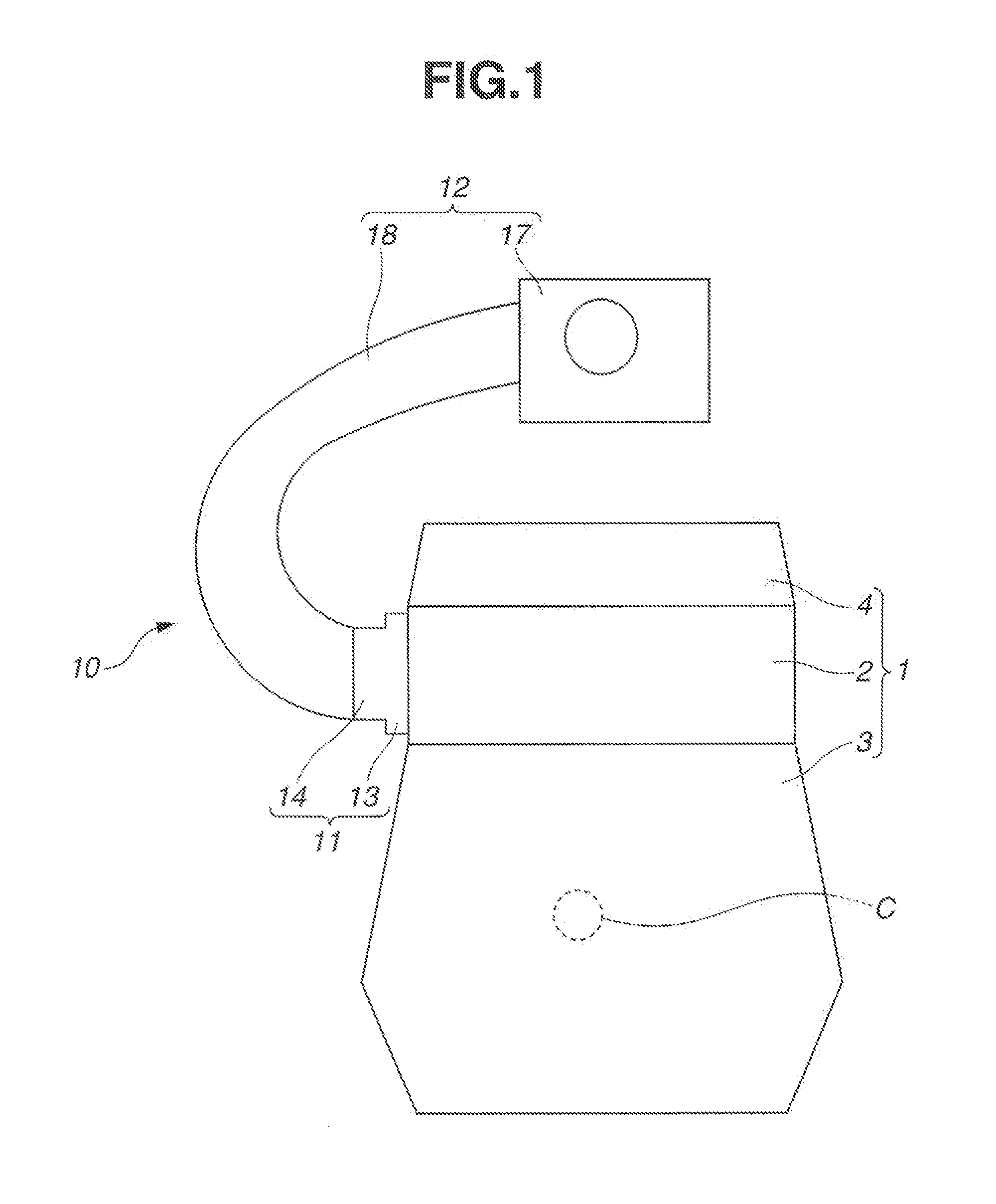
[0015]In the following, an intake manifold 10 of the present invention for an internal combustion engine 1 will be described in detail with reference to the accompanying drawings.

[0016]In the explanation, various directional terms such as right, left, upward, downward or the like are used for ease of description. However, such terms are to be understood with respect to only a drawing or drawings on which corresponding part or parts are shown.

[0017]In FIG. 1, there is schematically shown the intake manifold 10 practically applied to an inline-four-cylinder type internal combustion engine 1. As will be understood from this drawing, the intake manifold 10 is mounted to one of opposed side walls of the engine 1 with respect to a direction in which a crankshaft C of the engine 1 extends.

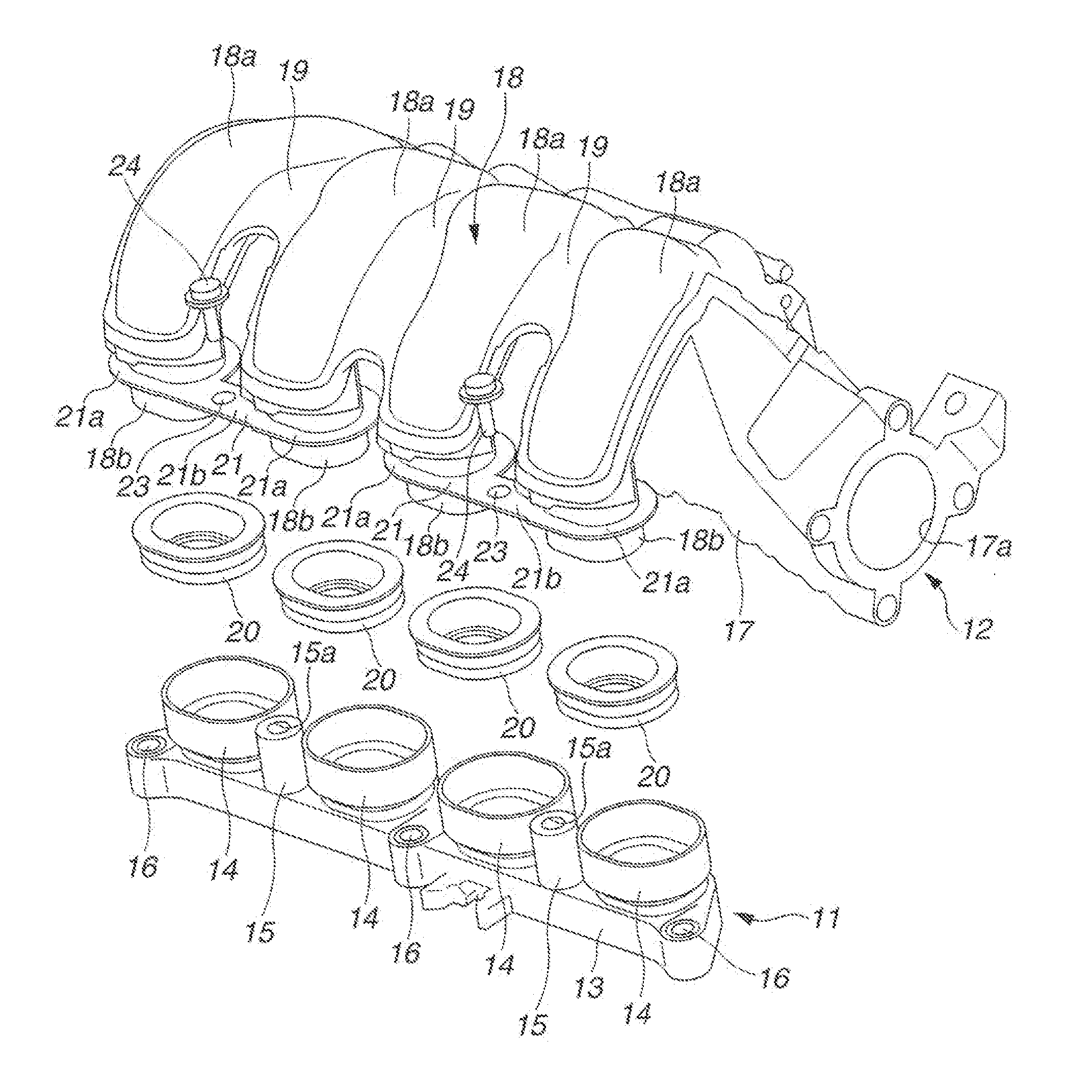
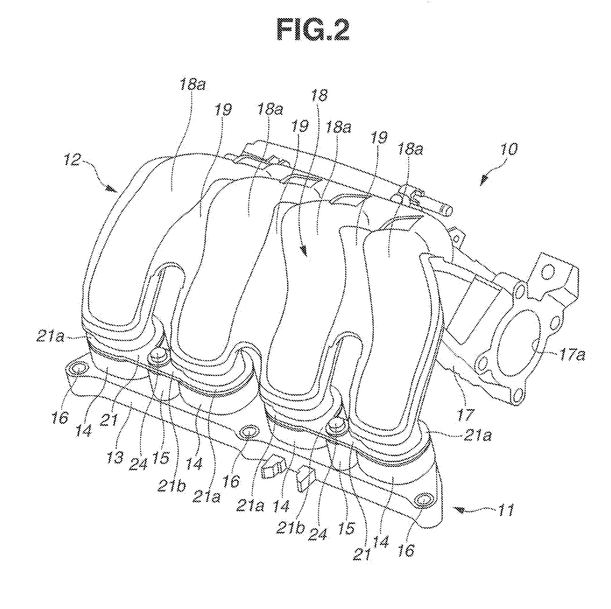
[0018]As is seen from FIGS. 1 and 2, the intake manifold 10 comprises generally a downstream unit 11 that is mounted to a cylinder head 2 of the engine 1 through connecting bolts (not shown) and an upstre...


PUM

PropertyMeasurementUnit
Electrical resistanceaaaaaaaaaa
Thermal resistanceaaaaaaaaaa

Abstract

An intake manifold for an internal combustion engine, comprises an upstream unit of molded resin, the upstream unit including an elongate collector portion that has an inlet opening for introducing cleaned air, and a manifold portion that includes a plurality of curved tubes that are fixed to one another, each curbed tube having an inlet opening exposed to an interior of the elongate collector portion; a downstream unit of molded resin, the downstream unit including a base portion that is to be connected to a cylinder head of the engine and a plurality of apertured collar portions that are projected from the base portion; and a plurality of sealing members through which leading ends of the curved tubes are hermetically inserted into the apertured collar portions thereby to constitute an entire construction of the intake manifold, wherein the molded resin of the downstream unit has a heat resistance that is higher than that of the upstream unit.

Description

BACKGROUND OF THE INVENTION[0001]1. Field of the Invention[0002]The present invention relates in general to intake manifolds for an internal combustion engine, and more particularly to the intake manifolds of a type that is made of molded resin. More specifically, the present invention is concerned with the intake manifolds of a split type that includes an upstream unit of molded resin and a downstream unit of molded resin, both of which are coupled together to constitute an entire construction of the Intake manifold.[0003]2. Description of the Related Art[0004]In order to clarify the present invention, one conventional intake manifold of the above-mentioned type, namely, the intake manifold disclosed in Japanese Laid-open Patent Application (tokkai) 2009-74509 will be briefly described in the following.[0005]The Intake manifold disclosed by the above-mentioned published application is of the split type comprising a serge tank portion that is constructed of molded resin and a tube c...

Claims


Application Information

Patent Timeline
IPC IPC(8): F02M35/10F02M35/104
CPCF02M35/104F02M35/10321F02M35/10347F02M35/10354F02M35/112F02M35/10052F02M35/10085F02M35/10091F02M35/10144F16L39/00
Inventor HORII, KIYOHIDE
Owner MAHLE FILTER SYST JAPAN CORP
Why Eureka
Try Eureka