Autonomous, Gravity-Assisted Motorized Racer Configured To Travel Through Non-Straight Tube Segments

a technology of gravity-assisted motors and tube segments, which is applied in the direction of toy trackways, remote-control toys, toys, etc., can solve the problems of practicable limits or constraints on how convoluted the track can be formed

Active Publication Date: 2018-02-15
DREW JORDAN CORP
View PDF12 Cites 7 Cited by
  • Summary
  • Abstract
  • Description
  • Claims
  • Application Information

AI Technical Summary

Benefits of technology

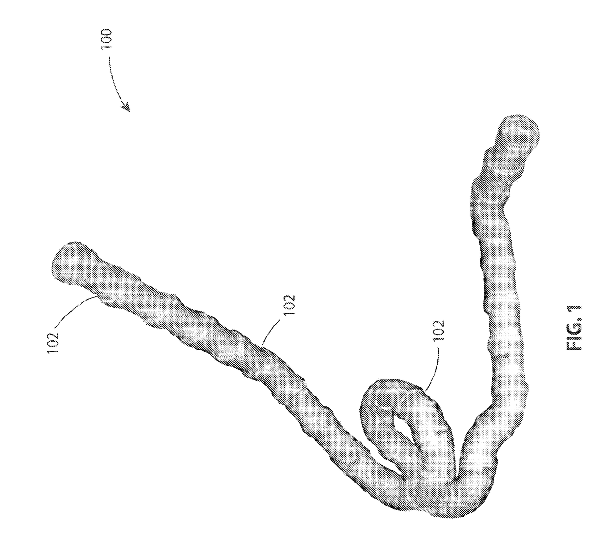
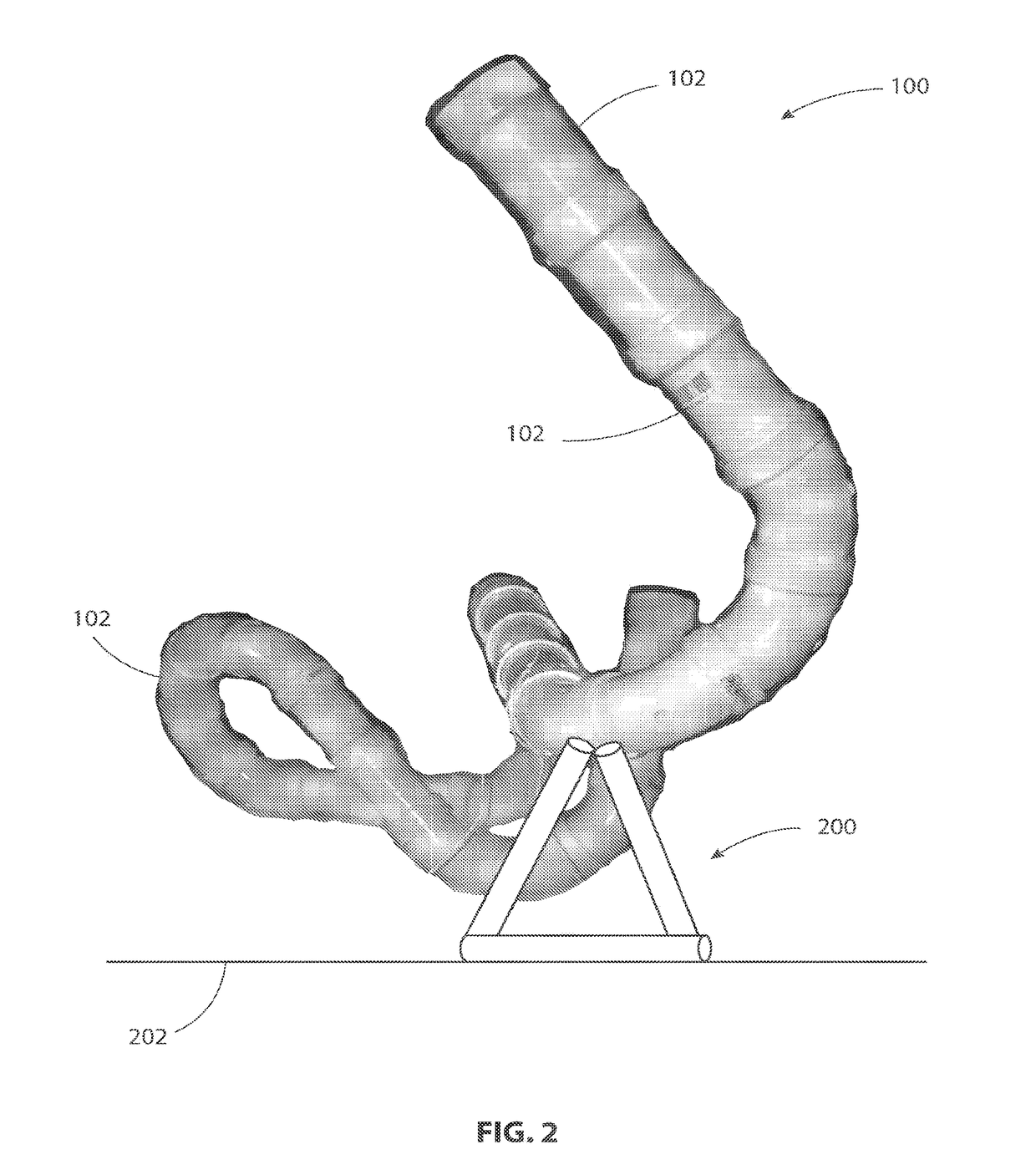
[0004]A tube assembly is disclosed that includes curved tubes or tube segments that are connected together, and they can be connected and rotated in virtually an unlimited number of configurations. Variations on the tube segments, as well as support post or structures to support the assembled tube configuration, are also disclosed. The tubes or tube segments can snap together (e.g., via one or more tube-couplers) to prevent horizontal sliding.
[0005]An autonomous, gravity-assisted motorized toy racer vehicle is also disclosed having a form factor and geometry that allows the vehicle to be able to navigate autonomously inside the tubes without getting stuck, while maintaining drive contact with the inside of the tubes surface (even if sideways or upside down relative to earth). By “autonomous” it is meant that the racer vehicle does not require any manual human energy to impart forward momentum to the vehicle. The autonomous vehicle disclosed herein can be operated by remote control, or it can be automatically controlled.
[0006]The tube segments are assembled together to form a tube assembly to form a desired racing path for the racer vehicle. Thus, there are at least two play components: construction and play. The tube assembly provides the construction component, and racing the motorized racer vehicle through the tubes provides the play component. The racer vehicle includes a battery and a motor powered by the battery. The motor is connected to a wheel that propels the racer vehicle through the tubes, but the racer vehicle also gains speed from gravity when heading in a direction back toward earth. The motorized component allows the racer vehicle to go in a direction opposite earth or transverse to earth.

Problems solved by technology

The tracks are open, which means that the cars frequently come off the tracks, and there is a practical limit or constraint on how convoluted the track can be formed due to the reliance upon gravity and that the car can succumb to gravity and come off the track, particularly when ascending vertically, undergoing a twisting or rotational motion, or looping around a loop section of the track.

Method used


Image

  • Autonomous, Gravity-Assisted Motorized Racer Configured To Travel Through Non-Straight Tube Segments
  • Autonomous, Gravity-Assisted Motorized Racer Configured To Travel Through Non-Straight Tube Segments
  • Autonomous, Gravity-Assisted Motorized Racer Configured To Travel Through Non-Straight Tube Segments

Examples


embodiment 1

[0082) Helical Gear Drive is more normal in the tube and on the floor.

embodiment 2

[0083) Belt Drive. It will be very strange on the ground as the spine will not be horizontal in many possible configurations. The belts can also be replaced with a train of idler gears if gears are preferred to belt.

[0084]FIG. 22 illustrates a vehicle featuring a helical gear drive 2200 (Embodiment 1). The helical gear drive embodiment features:

[0085]A) A central drive gear directly coupled to the motor 2206, and 3 equally spaced driven gears 2204.

[0086]B) The driven gears are over-molded with rubber tires that straddle the central gear.

[0087]C) The drive housing is split for assembly. The motor 2206 snaps into the drive housing and connects to the central gear.

[0088]D) The associated electronics, connectors, PCB, batteries, etc. can nest in the voids around the motor or on a cage frame around the motor.

[0089]E) This arrangement allows any two wheel tangencies to drive on a flat surface, and allows space within to house a modestly sized vehicle body. If a non-flat surface vehicle is...


PUM


Abstract

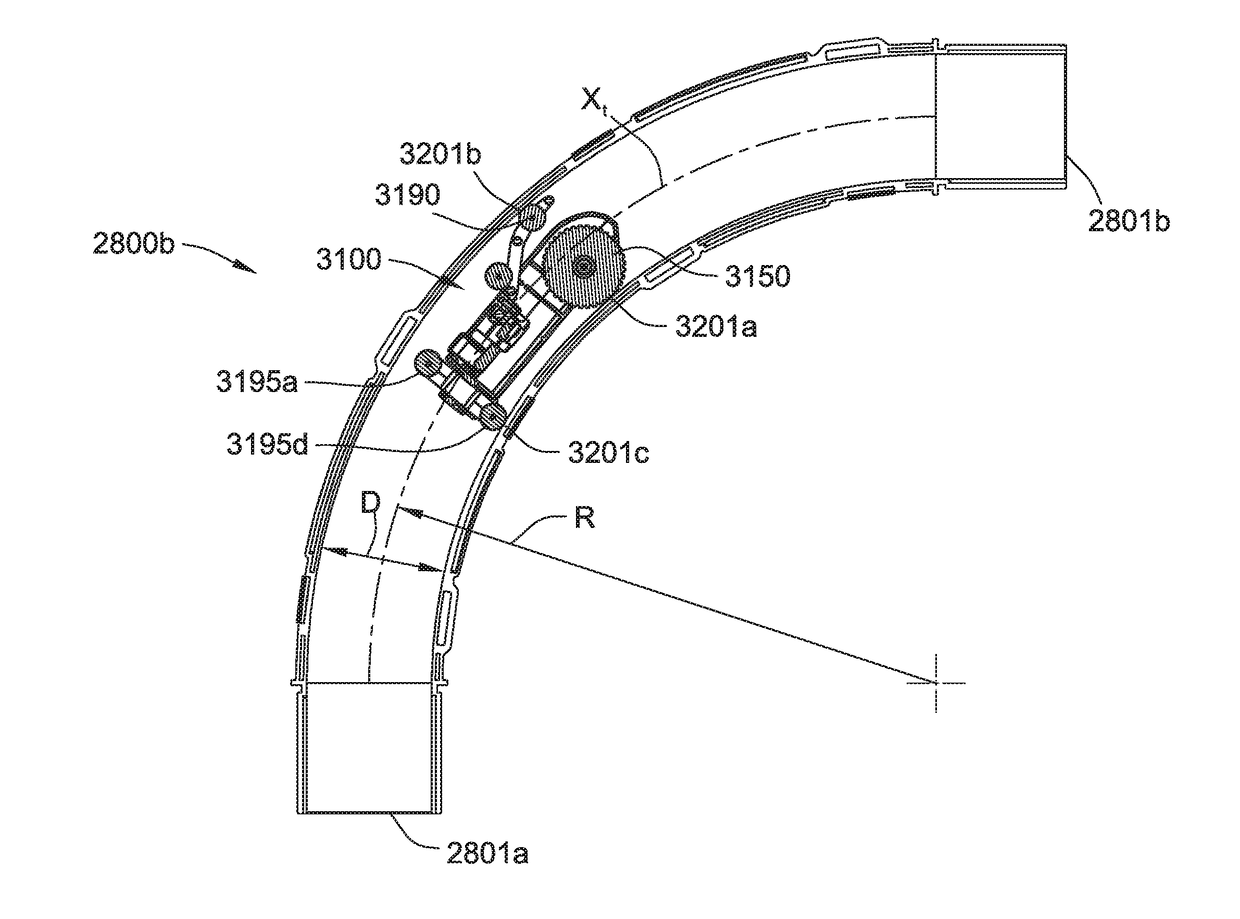
A vehicle configured to move through a network of interconnected tubes includes a body, a motor, a motorized wheel, a biasing assembly, and a first element. The motorized wheel directly engages an inner surface of the tubes. The biasing assembly causes the motorized wheel to maintain continuous contact with the inner surface of the tubes during operation. A waist of the vehicle is constrained by an inner diameter (D) of the curved tube, a radius of curvature (R) of the curved tube, and a length (L) of the wheelbase of the vehicle. The waist of the body is sized such that the vehicle can freely move within any of the tubes without getting stuck therein.

Description

CROSS-REFERENCE TO RELATED APPLICATIONS[0001]This application is a continuation-in-part of International Application No. PCT / US17 / 028565, filed Apr. 20, 2017, which claims priority to and the benefit of U.S. Provisional Application No. 62 / 325,293, filed Apr. 20, 2016, each of which is hereby incorporated by reference herein in its entirety.FIELD OF THE INVENTION[0002]Aspects of the present disclosure relate to autonomous, gravity-assisted motorized toy racers and tube assemblies through which the toy racers run.BACKGROUND OF THE INVENTION[0003]Kids love to race cars. Conventionally, cars are raced on tracks, which can be assembled together to form a variety of configurations. The tracks are open, which means that the cars frequently come off the tracks, and there is a practical limit or constraint on how convoluted the track can be formed due to the reliance upon gravity and that the car can succumb to gravity and come off the track, particularly when ascending vertically, undergoin...

Claims


Application Information

Patent Timeline
Patent Type & Authority Applications(United States)
IPC IPC(8): A63H18/02A63H17/00A63H17/34A63H17/26A63H17/28A63H30/04A63H17/14
CPCA63H18/02A63H18/028A63H30/04A63H17/004A63H17/14A63H17/262A63H17/28A63H17/34A63H18/04A63H18/08A63H33/105A63H33/106A63H2018/165
Inventor FARRELL, DIANE M.LYNCH, JASON M.RASMUSSEN, JAMES M.ROTHSCHILD, MAXWELL B.ROTHSCHILD, WAYNE H.
Owner DREW JORDAN CORP
Why Eureka
Try Eureka