
Guide tube for microsurgical instruments

a microsurgical instrument and guide tube technology, applied in the field of guide tubes for active surgical instruments, can solve the problems of long operation time, inability to direct approach and manipulate in many cases by using existing linear surgical instruments, and often restricted approach to the lesion, so as to achieve simple operation and processing, and enhance strength

Inactive Publication Date: 2014-02-06
KOREA INST OF SCI & TECH
View PDF8 Cites 7 Cited by
  • Summary
  • Abstract
  • Description
  • Claims
  • Application Information

AI Technical Summary

Benefits of technology

The present invention provides a guide tube for microsurgical instruments with a curved tube that can be bent to support surgical instruments. The guide tube has a linear tube with a hollow, a curved tube mounted at the front of the linear tube, an elastic body that increases the gap between the unit bodies, and a tension control unit that bends the curved tube by controlling the tensions of wires extending from the curved tube. The guide tube allows for easy operation and processing, and the connection portion of cylinders is configured with a ball and a socket.

Problems solved by technology

Therefore, the approach to the lesion is often restricted without a specially developed instrument.
In particular, even though the spot of the lesion is visually checked by using a fixed-angle endoscopy or the like, direct approach and manipulation is impossible in many cases by using existing linear surgical instruments.
However, the former method takes a long operation time and greatly depends on the experiences and skill level of an operator, and the later method is a major surgery consuming about 10 hours or more, which frequently causes postoperative complications, lengthens the recovery period and remains great surgical scars.
In this regard, instruments used for the single port laparoscopic surgery implement the curve of their terminals by using wires or the like for the manipulation in a narrow work space, but their diameter is too great to be used for microsurgeries of the neurosurgery.

Method used


Image

  • Guide tube for microsurgical instruments
  • Guide tube for microsurgical instruments
  • Guide tube for microsurgical instruments

Examples


Embodiment Construction

[0039]Hereinafter, a guide tube for microsurgical instruments according to exemplary embodiments of the present disclosure will be described in detail with reference to the accompanying drawings.

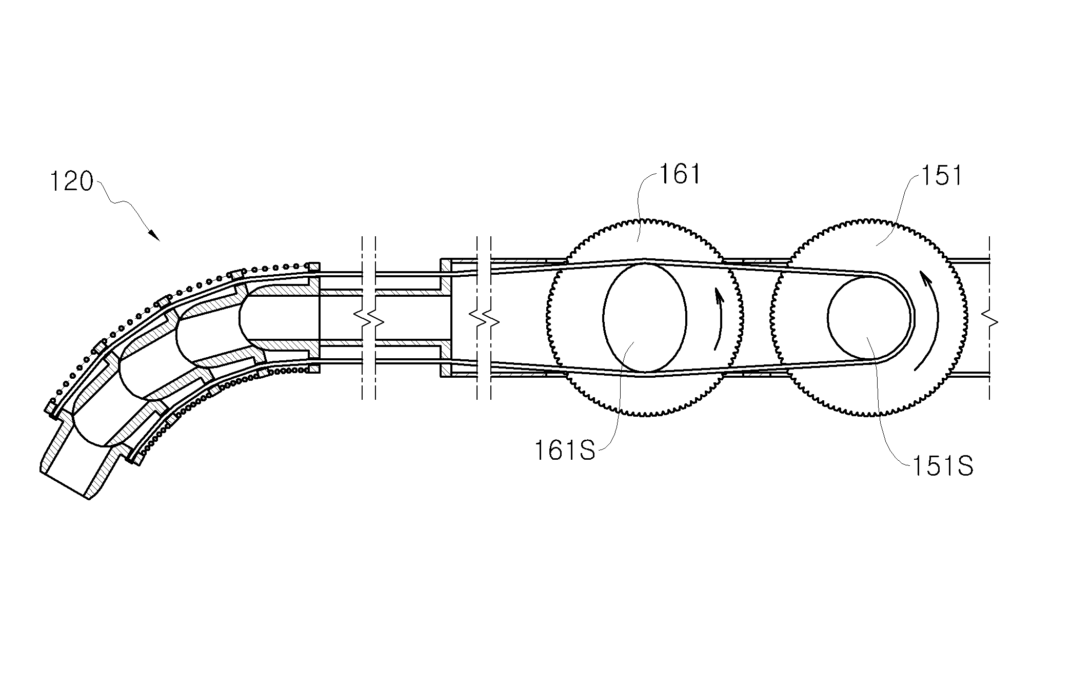
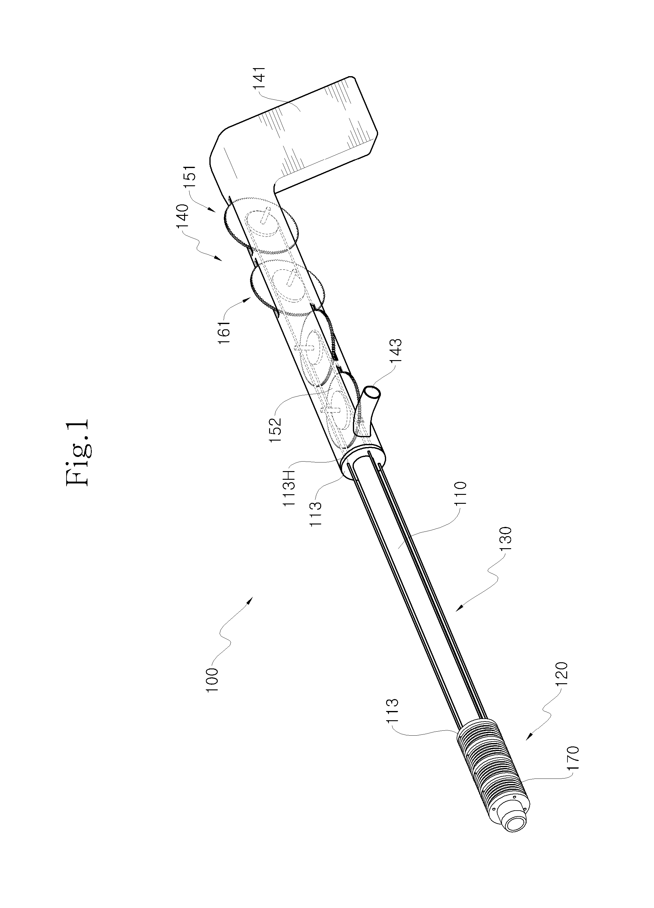
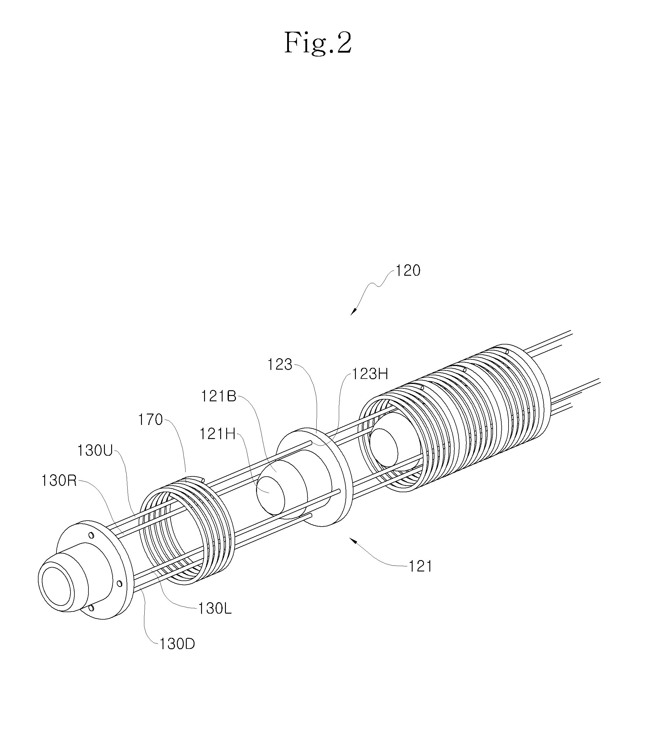
[0040]In the drawings, FIG. 1 is a perspective view showing a guide tube for microsurgical instruments according to the present disclosure, FIG. 2 is an exploded perspective view showing a terminal of the guide tube of FIG. 1, FIG. 3 is a cross-sectional view showing the guide tube of FIG. 1, FIG. 4 is a detailed diagram showing a coupling relation among a coil spring, a flange and a wire hole employed in the guide tube of FIG. 1, FIG. 5 is a cross-sectional view showing the terminal of the guide tube of FIG. 1 which is in a bending state, FIG. 6 is a conceptual diagram showing a microsurgical instrument inserted into the guide tube of FIG. 5, FIG. 7 is a detailed diagram showing a tension control unit employed in the guide tube of FIG. 1, and FIGS. 8A and 8B are conceptual diagrams showing ...


PUM


Abstract

A guide tube for microsurgical instruments has a linear tube having a hollow formed in the length direction thereof, a curved tube mounted to the front end of the linear tube and having unit bodies connected to allow bending, an elastic body for giving an elastic force so that a gap between the unit bodies increases, and a tension control unit mounted to the rear end of the linear tube to bend the curved tube by controlling tensions of a plurality of wires extending from the curved tube, wherein the tension control unit controls the tensions of the wires in a state where the curved tube is curved so that the rigidity of the curved tube increases to support a surgical instrument located in the linear tube and the curved tube.

Description

CROSS-REFERENCE TO RELATED APPLICATION[0001]This application claims priority to Korean Patent Application No. 10-2012-0085082, filed on Aug. 3, 2012, and all the benefits accruing therefrom under 35 U.S.C. §119, the contents of which in its entirety are herein incorporated by reference.BACKGROUND[0002]1. Field[0003]The present disclosure relates to a guide tube for active surgical instruments, and more particularly, to a guide tube configured to allow bending of a terminal of a surgical instrument to be used for the minimally invasive surgery of a neurosurgery and also allow the rigidity to change so that a specific shape may be maintained.[0004]2. Description of the Related Art[0005]In the field of neurosurgery, the intracranial surgery using the minimally invasive method such as a transsphenoidal approach frequently demands minute manipulations in a deep and narrow work space. Therefore, the approach to the lesion is often restricted without a specially developed instrument.[0006]...

Claims


Application Information

Patent Timeline
IPC IPC(8): A61M25/01
CPCA61M25/0147A61M25/0136A61M25/0138A61B2017/00314A61B2017/00327A61B17/3421A61B17/34A61M25/09A61B17/00A61B17/29
Inventor KIM, SEUNG JONGOH, KYUNG GEUNEKIM, SEUNG BINKANG, SUNG CHUL
Owner KOREA INST OF SCI & TECH
Learn More