Ticket dispenser

a ticket dispenser and ticket technology, applied in the field of ticket dispensers, can solve the problem that tickets that have been separated from the main ticket ribbon are no longer able to be dispensed, and achieve the effect of improving the flow of tickets

Active Publication Date: 2019-03-26
FASTRAK RETAIL UK
View PDF14 Cites 0 Cited by
  • Summary
  • Abstract
  • Description
  • Claims
  • Application Information

AI Technical Summary

Benefits of technology

[0011]The storage chamber guide may comprise a fixed curved member spaced apart from the display wall. The fixed curved member may be fully or partially cylindrical or arcuate. If formed from sheet material, the fixed curved member may have an external radius of curvature of at least twice the thickness of the sheet material. The fixed curved member may be a curved end of a baffle. The fixed curved member may be provided in a central region of the ticket storage chamber. Advantageously, being gently curved enhances ticket flow past the fixed curved member.
[0012]The storage chamber guide may extend to at least 2 cm from the ticket display pathway. The storage chamber guide may extend to at least 2 cm from the display wall. The storage chamber guide may extend to at least 3 cm from the ticket display pathway. The storage chamber guide may extend to at least 3 cm from the display wall. Advantageously, spacing out tickets in the ticket storage chamber at the storage chamber guide enhances the flow of tickets towards the pathway inlet, and spacing out by at least 2 cm or at least 3 cm from the ticket display pathway or from the display wall may be particularly suitable for use tickets that are 10 to 25 cm long (or arranged in a ticket pack with pleats that are 10 to 25 cm long).
[0014]The storage chamber guide may extend to a maximal separation from the ticket display pathway at a location that is separated from the first wall by at least one third of the separation between the pathway inlet and the first wall and by less than two thirds of the length of the chamber. The storage chamber guide may extend to a maximal separation from the display wall at a location that is separated from the first wall by at least one third of the separation between the pathway inlet and the first wall and by less than two thirds of the length of the chamber. Advantageously, such location of the maximal separation of the storage chamber guide enables the storage chamber guide to support the ticket pack, if required (e.g. for shorter or less resilient tickets), and to influence the flow of tickets as they are drawn away from the main body of the ticket pack, during dispensing, to reduce the risk of tickets becoming jammed or damanged.

Problems solved by technology

Disadvantageously, a ticket that has been separated from the main ribbon of tickets is no longer able to be dispensed through the dispensing aperture, and the retail staff must take care to remove it before loading the ticket dispenser with a ribbon of tickets of a different type.

Method used


Image

  • Ticket dispenser
  • Ticket dispenser
  • Ticket dispenser

Examples


Embodiment Construction

[0034]In the described embodiments, like features have been identified with like numerals, albeit in some cases having one or more of: increments of 100. For example, in different figures, 100, 200, 300 and 400 have been used to illustrate a ticket dispenser for dispensing a pleated ribbon of tickets.

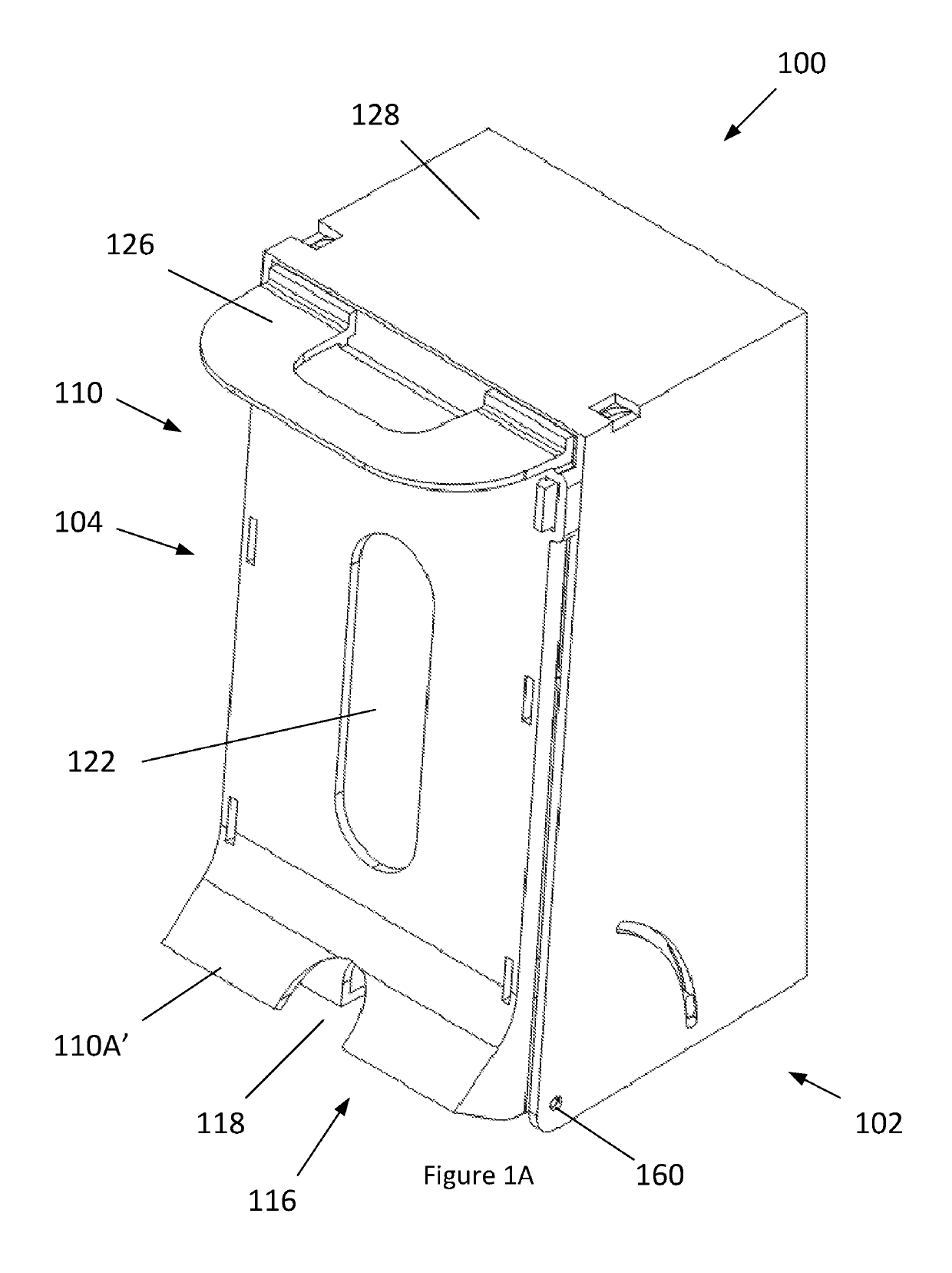
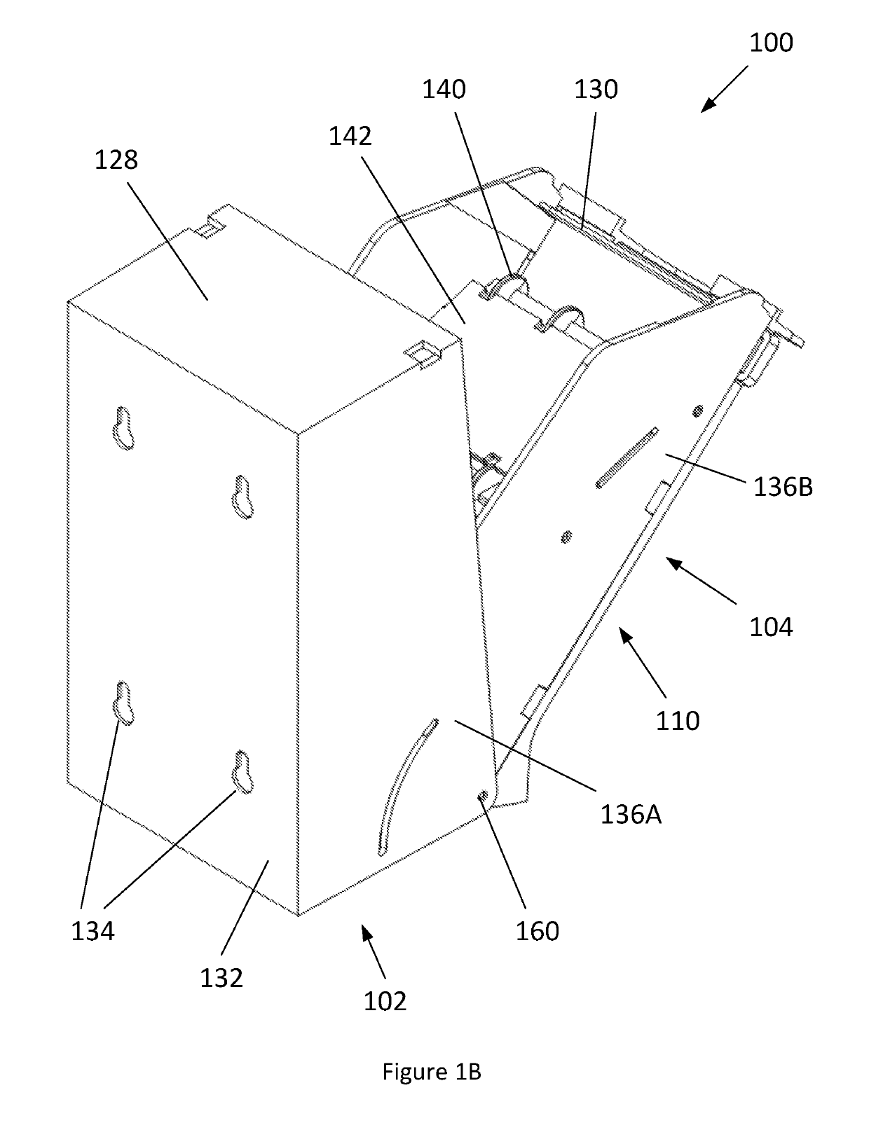
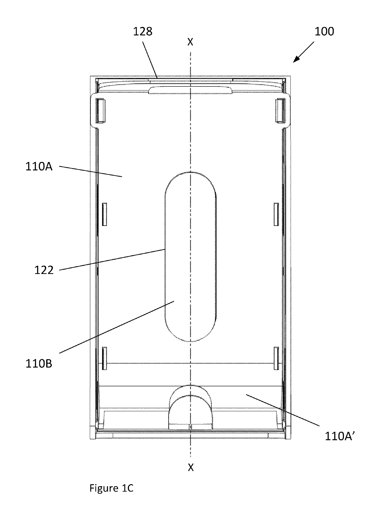
[0035]FIG. 1A shows perspective views of a ticket dispenser 100 comprising a housing formed by a box-like body 102 with an open end in which a door 104 is pivotably mounted, and FIG. 1B shows a perspective view in which the door is open. FIG. 10 shows a view of the ticket dispenser 100 facing towards the door 104, and FIG. 1D shows a cut-away view of the ticket dispenser corresponding to the section X-X that is indicated in FIG. 1C. FIGS. 1E to 1J illustrate the ticket dispenser 100 with a ticket pack 190 loaded into the ticket storage chamber 120, and the arrangement of the tickets 190′, 190″ and 190′″ during successive stages in the dispensing of a single ticket 190′ through the dispe...


PUM


Abstract

A ticket dispenser for dispensing a pleated ribbon of tickets, the ticket dispenser comprising a ticket storage chamber within a housing and a ticket dispensing aperture, wherein the housing has opposed ticket display and rear walls, and also has opposed first and second walls that each extend between the ticket display wall and the rear wall, the display wall comprising: an outer wall having an interior face, and an inner ticket pathway guide proximate the outer wall, providing a ticket display pathway extending along the interior face of the outer wall, between the outer wall and the inner ticket pathway guide, the ticket display pathway having a pathway inlet, wherein the ticket dispenser is configured for a ticket to be drawn out from within the storage chamber, through the pathway inlet, along the ticket display pathway towards the first wall, and out through the dispensing aperture, wherein the ticket storage chamber has a chamber length extending along the display wall between the first wall and the second wall, and the ticket display pathway extends along more than half of the chamber length, wherein the ticket storage chamber is provided with a storage chamber guide configured to space tickets apart from the display wall adjacent a central portion along the length of the ticket display pathway, and wherein the storage chamber guide extends to a maximal separation from the ticket display pathway at a location that is closer to the first wall than the separation between the pathway inlet and the first wall.

Description

[0001]This application is a national stage application under 35 U.S.C. § 371 of PCT Application No. PCT / GB2015 / 053298, filed Nov. 2, 2015, which claims the benefit of Great Britain Application No. 1419490.6, filed Oct. 31, 2014. The entire contents of each of PCT Application No. PCT / GB2015 / 053298 and Great Britain Application No. 1419490.6 are incorporated herein by reference in their respective entireties.FIELD OF INVENTION[0002]The present invention relates to ticket dispensers for use with a pleated ribbon of tickets.BACKGROUND[0003]WO2013041858A1 discloses a ticket dispenser suitable for dispensing tickets from a ribbon of tickets arranged in a pleated pack, in which a first ticket is dispensed to a retailer approximately perpendicular to a front dispensing face of the ticket dispenser. An exemplary ticket may be displayed to a customer through a back face of the ticket dispenser, and the ticket dispenser may be mounted on a retail counter, in which the retailer and customer fac...

Claims


Application Information

Patent Timeline
Patent Type & Authority Patents(United States)
IPC IPC(8): B65D83/12G07B3/04G07B7/00B65D83/08G07B1/00
CPCG07B3/04B65D83/0864G07B7/00G07B1/00B65D83/12
Inventor SHARDLOW, PAULMATTHEWS, STEPHEN
Owner FASTRAK RETAIL UK
Why Eureka
Try Eureka