Supercharge Your Innovation With Domain-Expert AI Agents!

Control valve having an outflow channel

a control valve and outflow channel technology, applied in the direction of lift valves, valve details, engine components, etc., can solve the problem of no longer being used for other purposes

Inactive Publication Date: 2019-04-02
SCHAEFFLER TECH AG & CO KG
View PDF15 Cites 0 Cited by
  • Summary
  • Abstract
  • Description
  • Claims
  • Application Information

AI Technical Summary

Benefits of technology

This design optimizes installation space and manufacturing costs by allowing flexible placement of the outflow connection without restricting other hydraulic medium paths, enhancing the control valve's efficiency and adaptability within the engine.

Problems solved by technology

However, the described hydraulic medium path generally requires a shared pressure medium line through the piston cavity, which, as a hydraulic medium path, therefore can no longer be utilized for other purposes.

Method used


Image

  • Control valve having an outflow channel
  • Control valve having an outflow channel

Examples


Embodiment Construction

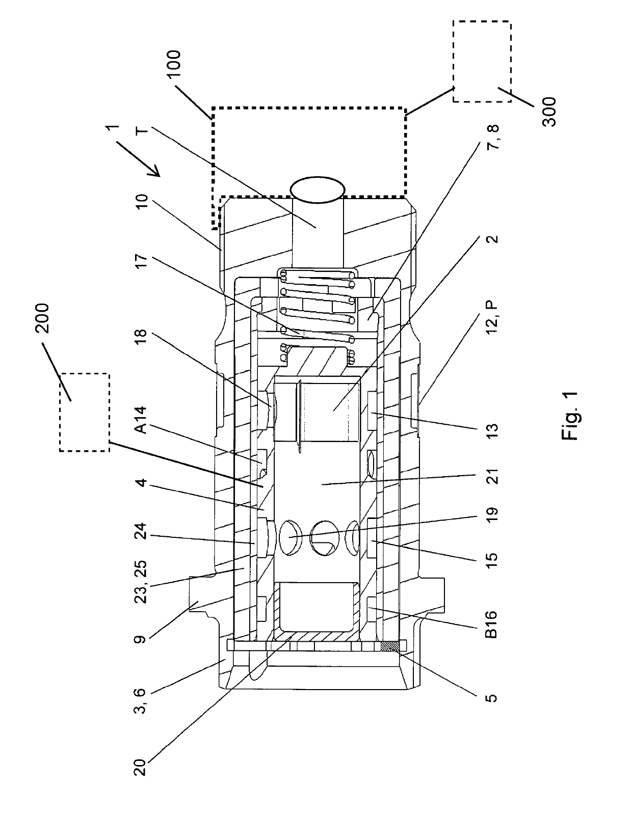
[0021]FIG. 1 shows in the longitudinal section one specific embodiment, by way of example, of a control valve 1 which includes a check valve 2. Control valve 1 is made up of a valve housing 3 and a hollow cylindrical control piston 4 that is axially movably guided in a corresponding cavity in valve housing 3. The adjustment range of control piston 4 is axially delimited by a locking ring 5 on first end 6 and by an end element 7 on second end 8. Valve housing 3 may be accommodated by a cavity in a camshaft 100 and used for controlling a camshaft adjuster 200 for an internal combustion engine 300. A flange 9 together with an external thread 10 is used to connect control valve 1 to the camshaft 100. Valve housing 3 has three openings on its outer circumference: The openings form inflow connection P, as well as first supply connection A, and second supply connection B. An outflow connection T is situated at second end 8 of the valve housing. A filter 12 is situated in the area of the op...


PUM


Abstract

A control valve (1) for a camshaft adjustment device, and to an internal combustion engine having a camshaft adjustment device and a control valve (1) is provided. The control valve (1) includes a valve housing (3) and a pressure medium guiding insert (23) arranged coaxially in a recess of the valve housing (3). A discharge passage (27, 28) of the pressure medium guiding insert (23) transitions into a discharge duct (22) running in the axial direction, wherein the discharge connection T can be connected to the control connections A, B and wherein the discharge connection T is arranged in a region between the second end (8), which is opposite the first end (6), and the control connections A, B.

Description

[0001]The present invention is directed to the field of proportional directional control valves, which may be used as a central valve, in particular for controlling so-called camshaft adjusters. Camshaft adjusters are used for controlling the operation of an internal combustion engine by influencing the charge cycle in a targeted manner: An adjustment of the phase position of the camshaft changes its position in relation to the phase position of the crankshaft; the opening and closing times of the gas exchange valves may thus be shifted to an earlier or later point in time of the run-through cyclical process. Central valves have multiple switching positions, with the aid of which the course of a pressure medium path may be adjusted between an inflow and an outflow; the pressure medium flow exerts a force on the camshaft adjuster that is a function of the switching position, and effectuates an adjustment into a certain position.BACKGROUND[0002]DE 10 2009 024 026 A1 provides a control...

Claims


Application Information

Patent Timeline
Patent Type & Authority Patents(United States)
IPC IPC(8): F01L1/344F16K1/36F16K31/06F01L1/46
CPCF01L1/3442F01L1/344F16K1/36F16K31/0613F01L2101/00F01L1/46F01L2001/3443F01L2001/34433F01L2301/00
Inventor KOEHLER, DAVIDHOPPE, JENS
Owner SCHAEFFLER TECH AG & CO KG
Features
  • R&D
  • Intellectual Property
  • Life Sciences
  • Materials
  • Tech Scout
  • Unparalleled Data Quality
  • Higher Quality Content
  • 60% Fewer Hallucinations
Learn More