Power management for distributed communication systems, and related components, systems, and methods

Active Publication Date: 2019-04-09
CORNING OPTICAL COMM WIRELESS
View PDF536 Cites 11 Cited by
  • Summary
  • Abstract
  • Description
  • Claims
  • Application Information

AI Technical Summary

Problems solved by technology

When the power requirements exceed the available power, the RU may shut down and provide no services or may have other disturbances in the operation of the RU.

Method used


Image

  • Power management for distributed communication systems, and related components, systems, and methods
  • Power management for distributed communication systems, and related components, systems, and methods
  • Power management for distributed communication systems, and related components, systems, and methods

Examples


Embodiment Construction

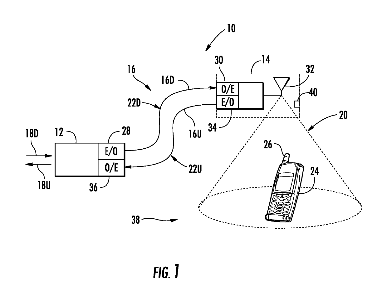
[0006]Embodiments disclosed in the detailed description include power management techniques in distributed communication systems. Related components, systems, and methods are also disclosed. In embodiments disclosed herein, services within a remote unit of the distributed communication system are selectively activated and power consumption is measured. From at least two measurements, a maximum power available may be calculated and compared to power requirements of the remote unit.

[0007]In this regard in one embodiment, a remote unit for use in a distributed communication system is disclosed. The remote unit comprises a first power input configured to receive a first power signal from a power distribution module through a first power medium. The remote unit also comprises a power sensor configured to measure power from the first power input. The remote unit also comprises a control system configured to activate services in the remote unit selectively such that at least two power cons...


PUM


Abstract

Power management techniques in distributed communication systems are disclosed herein. Related components, systems, and methods are also disclosed. In embodiments disclosed herein, services within a remote unit of the distributed communication system are selectively activated and power consumption is measured. From at least two measurements, a maximum power available may be calculated and compared to power requirements of the remote unit.

Description

FIELD OF THE DISCLOSURE[0001]The technology of the disclosure relates to managing power in remote units in a distributed communication system.TECHNICAL BACKGROUND[0002]Wireless communication is rapidly growing, with ever-increasing demands for high-speed mobile data communication. As an example, so-called “wireless fidelity” or “WiFi” systems and wireless local area networks (WLANs) are being deployed in many different types of areas. Distributed antenna systems communicate with wireless devices called “clients,” which must reside within the wireless range or “cell coverage area” in order to communicate with an access point device. One approach to deploying a distributed antenna system involves the use of radio frequency (RF) antenna coverage areas, also referred to as “antenna coverage areas.” Because the antenna coverage areas each cover small areas, there are typically only a few users (clients) per coverage area.[0003]One type of distributed antenna system for creating antenna c...

Claims


Application Information

Patent Timeline
Patent Type & Authority Patents(United States)
IPC IPC(8): H04L12/26H04W52/02
CPCH04L43/00H04W52/0206Y02D70/00Y02D70/166Y02D70/1242Y02D70/1262Y02D70/142Y02D70/1224Y02D30/70
Inventor HAZANI, AMIZILBERMAN, SHLOMO
Owner CORNING OPTICAL COMM WIRELESS
Why Eureka
Try Eureka