Disconnecting mechanisms

Active Publication Date: 2019-04-16
CONCEPTOMED AS
View PDF49 Cites 1 Cited by
  • Summary
  • Abstract
  • Description
  • Claims
  • Application Information

AI Technical Summary

Benefits of technology

[0015]Such a device provides a novel mechanism for locking with a screw fit and automatic release using a lever. The screw thread mounted on the lever member enables a hub carrying a screw thread, such as a standard Luer lock hub, to be connected to the device. The hub may be connected by relative rotation, as is conventional, to ensure a tight screw connection. Such a Luer lock connection may be suited to high pressure fluid transfer procedures. A benefit of the operating the lever member to pivot away the screw thread and release the screw fit is that a hub can be disconnected from the device without an unscrewing action. The usual two-handed operation of unscrewed can be replaced by a simple one-handed operation of the lever member. Such a device may furthermore be connected to a hub carrying a flange, such as a standard Luer slip hub, with the screw thread engaging the flange to provide a positive connection in addition to the friction fitting. Other hub designs may also be positively engaged by the screw thread, as is explained further below.
[0077]It is also envisaged that suitable hubs may deviate from standard Luer slip or Luer lock designs. The Applicant has recognised that when a hub is to be disconnected using a lever member it may be helpful to provide space below the outer rim or thread for the lever member to interact with the hub. Thus in a set of embodiments the hub comprises a tapered internal surface and an outer rim or thread spaced from its base by a skirt portion. The skirt portion can conveniently provide room for a lever member to rotate before it comes into contact with the rim or thread. As is described above, this may allow an internally threaded collar to open to release the screw fit before further movement of the lever member moves a front surface (e.g. having a rim) forwards along the fluid transfer tip, past the skirt portion, to release the hub from the friction fitting by pushing against the rim or thread. The skirt portion may be flexible.

Problems solved by technology

Simply releasing the screw fit is not enough to disconnect the hub from the fluid transfer tip; the hub cannot fall away from the tip under gravity due to the friction fitting.

Method used


Image

  • Disconnecting mechanisms
  • Disconnecting mechanisms
  • Disconnecting mechanisms

Examples


Embodiment Construction

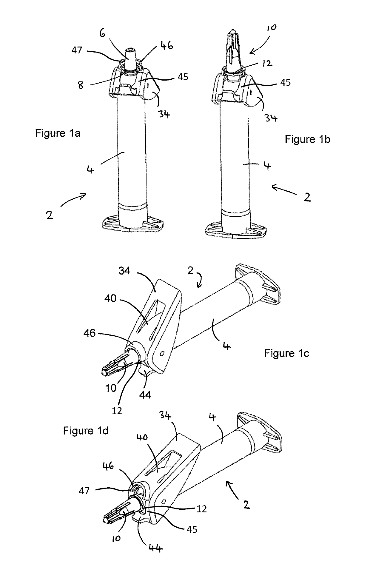
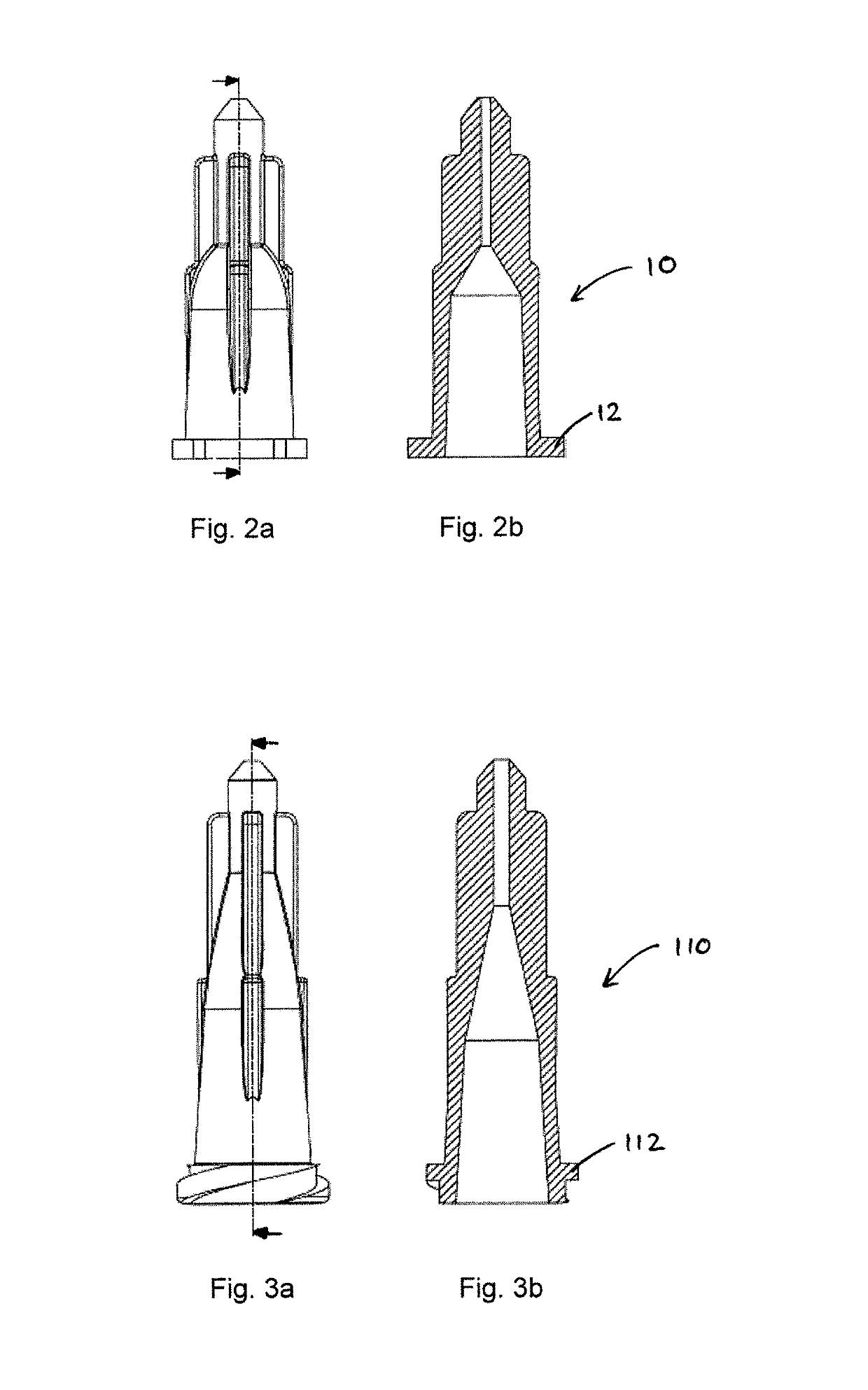
[0107]FIGS. 1a to 1d illustrate an embodiment of a disconnecting mechanism for a hub 10. The syringe 2 has a fluid transfer tip 6 that is tapered so as to form a Luer slip connection i.e. friction fitting with a corresponding hub 10. In addition the tip 6 may optionally be provided with an annular gripping flange 8 surrounding the tip 6 close to the barrel 4 of the syringe 2. The hub 10 may be a standard Luer slip hub 10 as seen in FIGS. 2a and 2b, or a hub 410 as seen in FIGS. 14a and 14b which includes an annular groove on its inner surface to grip onto the flange 8. The hub 10 may be similar to a standard Luer slip hub having an internal taper and an outer rim 12, except additionally provided with a skirt extending below the rim 12. Alternatively, the hub 10 may be a standard Luer lock hub 110 as seen in FIGS. 3a and 3b.

[0108]In this embodiment (see FIG. 1a) the syringe 2 has a pivotally mounted lever member 34 which carries a forwardly extending latch 46 in the form of a partia...


PUM


Abstract

A disconnecting mechanism includes a main body including a fluid transfer tip having a tapered surface to form a friction fit with a corresponding connector. The lever member includes a threaded portion to enable the corresponding connector part to be connected to the fluid transfer tip by a screw fit in addition to the friction fit, and an actuator portion to actuate release of the friction fit. In a first pivotal position, the threaded portion has a first position close to the fluid transfer tip to engage with an outer thread or rim of the corresponding part and thereby form the screw fit in addition to the friction fit. In a second pivotal position, the threaded portion has a second position further away from the fluid transfer tip to disconnect the screw fit and the actuator portion is moved forward to push the connector part and release the friction fit.

Description

TECHNICAL FIELD[0001]The present disclosure relates to the detachment of fluid-transferring devices and connections from a corresponding hub, and especially when transferring fluid in a medical setting. The disconnecting mechanisms, fluid transfer devices or fluid transfer connections as disclosed herein may find particular use in detaching a fluid transfer device such as a syringe, or other fluid transfer connection, from a hub that is connected to a living subject to / from whom fluid is being transferred.BACKGROUND OF THE INVENTION[0002]In a medical setting it may be necessary or desirable to transfer fluid to / from a subject for a variety of reasons. For example, a hub connected to a needle or other cannula may be used to draw blood from a vein or to infuse fluid substances i.e. intravenous (IV) therapy. A drip is one type of IV therapy. IV therapy may be used to correct electrolyte imbalances, to deliver medications or nutrition, for blood transfusion or as fluid replacement to co...

Claims


Application Information

Patent Timeline
Patent Type & Authority Patents(United States)
IPC IPC(8): A61M39/10
CPCA61M39/1011A61M39/1055A61M2039/1033A61M2039/1016A61M5/344A61M2005/3206
Inventor MIDE, CHRISTIANANDRESEN, MARIUSBLOMVAGNES, ROLFGEERS, KEVIN
Owner CONCEPTOMED AS
Why Eureka
Try Eureka