Vehicle-mounted conveyor system

a conveyor system and vehicle technology, applied in the direction of conveyor parts, transportation and packaging, supporting frames, etc., can solve the problems of inability to handle loose materials and typical articles of truck-mounted conveyors, and achieve the effect of facilitating the approach of dump trucks

Active Publication Date: 2019-08-22
MULTIELEVATOR
View PDF0 Cites 1 Cited by
  • Summary
  • Abstract
  • Description
  • Claims
  • Application Information

AI Technical Summary

Benefits of technology

[0011]It is another aspect of various embodiments of the present invention to provide a conveyor system that can serve as a small end “stacker” at road base recycling crushing sites. Some embodiments can include larger sized “stackers” for higher reach, but these embodiments may require a CDL-rated truck.
[0012]One aspect of various embodiments of the present invention is to provide a conveyor system with a novel mechanism that attaches to the channel frame rails of the transport vehicle. The manner of design of the entire mounting mechanism—less various standard components within it, such as the hydraulics and the rotator gear—is new and unique to the market. The mounting mechanism is designed to lift and hold the conveyor in a substantially horizontal position for road travel. When the conveyor is set up in its operating position, the mechanism lowers the infeed (bottom) end of the conveyor to the ground, elevates the discharge (top) end of the conveyor up to about a 30° to 45° incline, and rotates the conveyor up to 180° to the left or right.
[0013]Some embodiments of the present invention include a conveyor system with two independently driven conveyors: the main incline conveyor and a feed conveyor. In one embodiment, the feed conveyor is interconnected to the bottom end of the incline conveyor. For the travel position, the feed conveyor piggy backs onto the incline conveyor. For operation, the feed conveyor is lowered off of the incline conveyor via a track and trolley system (also called a “trolley rail system” herein). The feed conveyor can pivot approximately 90° relative to the incline conveyor in either direction to facilitate the approach of dump trucks loading directly onto the feed conveyor. The track and trolley system then returns the feed conveyor onto the incline conveyor for transport.
[0014]It is one aspect of embodiments of the present invention to provide a conveyor system that can place gravel or rock onto flat top roofs. Some embodiments can place the gravel or rock on roofs that are over 30 feet tall, while other embodiments are designed for roofs that are less than 30 feet tall. Additional embodiments include a conveyor system that can place dirt, landscape rock, and backfill into hard-to-reach places such as behind newly constructed retaining walls or landscape planters. Some embodiments include a conveyor to serve odd applications that arise, such as filling a coffer dam with dirt.
[0015]It is also an aspect of the present invention to provide a conveyor system comprising a conveyor belt, support elements to support the articles being conveyed, a support frame for the belt and to raise the conveyor belt upward, and a power source. The conveyor belt may include sections secured together, one or more pieces of belt material, strengthening mechanisms either below or between the one or more pieces of belt material to support the support elements, an upper surface, and an under surface. The power source may comprise electrical components and a motor. Note that the terms “cleat,”“flight,” and “support element” can be used interchangeably herein.
[0016]In some embodiments, the conveyor may be specially designed to move articles (including bricks, tiles, roofing materials, dirt, tires, etc.) upwardly at incline angles up to 60 degrees.

Problems solved by technology

Further, truck-mounted conveyors typically convey articles and cannot handle loose materials.

Method used


Image

  • Vehicle-mounted conveyor system
  • Vehicle-mounted conveyor system
  • Vehicle-mounted conveyor system

Examples


Embodiment Construction

[0055]Although the following text sets forth a detailed description of numerous different embodiments, it should be understood that the legal scope of the description is defined by the words of the claims set forth at the end of this disclosure. The detailed description is to be construed as exemplary only and does not describe every possible embodiment since describing every possible embodiment would be impractical, if not impossible. Numerous alternative embodiments could be implemented, using either current technology or technology developed after the filing date of this patent, which would still fall within the scope of the claims.

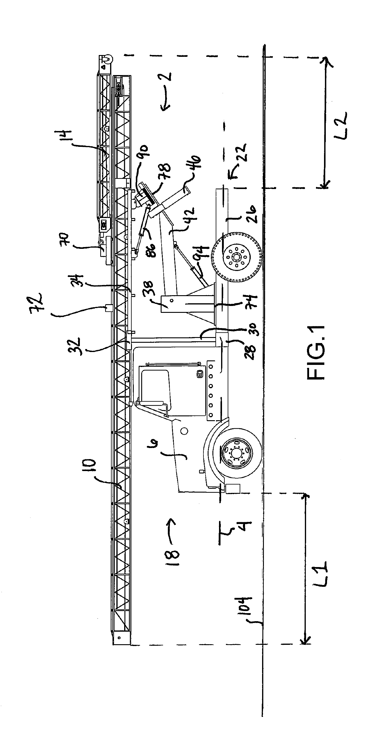
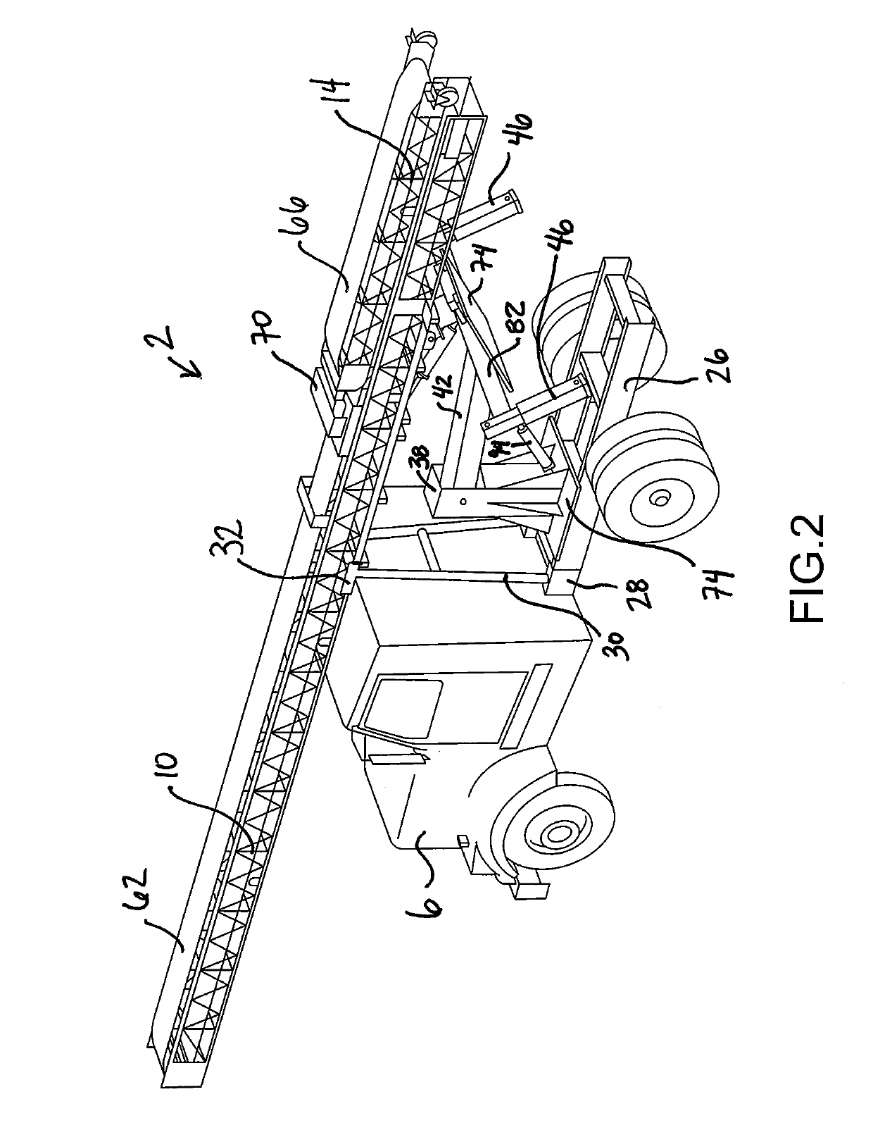
[0056]FIGS. 1 and 2 show an embodiment of a conveyor system 2 mounted on a vehicle 6 and in the road-travel position. FIG. 1 is a side elevation view of the conveyor system 2 and FIG. 2 is a rear perspective view. The vehicle 6 is positioned on the ground 104. The conveyor system 2 can be ultra-portable for aggregate stacking and transloading. In one e...


PUM


Abstract

Embodiments of the present invention generally relate to a vehicle-mounted conveyor system, and more specifically a maneuverable and mobile system interconnected to a motor vehicle, such as a truck, for conveying products and material. In some embodiments, the conveyor system comprises: a first conveyor; a second conveyor; a conveyor mount, wherein the first conveyor is interconnected to the conveyor mount; a first plate; a second plate; a post interconnected to the first plate; an arm member interconnected on one end to the post and interconnected on a second end to the second plate; a first hydraulic cylinder interconnected to the post and the arm member; a rotator gear interconnected to the second plate and the conveyor mount; a second hydraulic cylinder interconnected to the conveyor mount and the rotator gear; and a vehicle stabilizer, wherein the conveyor system has a first travel position and a second deployed position.

Description

CROSS REFERENCE TO RELATED APPLICATIONS[0001]This application claims the benefit of U.S. Provisional Application No. 62 / 710,448, filed on Feb. 16, 2018, entitled “Vehicle-Mounted Conveyor System,” the entire disclosure of which is incorporated by reference herein.FIELD OF THE INVENTION[0002]Embodiments of the present invention generally relate to a vehicle-mounted conveyor system, and more specifically to a maneuverable and mobile system interconnected to a motor vehicle, such as a truck, for conveying products and material.BACKGROUND OF THE INVENTION[0003]Conveyors are typically used at one site and rolled around on wheels to move from specific location to location within the site. Conveyors typically cannot rotate right to left to change the orientation of the conveyor. Few conveyors exist that are interconnected to a vehicle such that they can be used at various sites, e.g., construction sites.[0004]Truck-mounted conveyors usually require a CDL-rated truck. Further, truck-mounted...

Claims


Application Information

Patent Timeline
Patent Type & Authority Applications(United States)
IPC IPC(8): B65G41/00
CPCB65G41/001B65G41/00B65G41/002
Inventor BACON-MALDONADO, III, JOBDROST, ROBERT D.MILLER, CHRIS K.DROST, KENNETH B.MALDONADO, JR., JOBENSOR, KENTON C.
Owner MULTIELEVATOR
Why Eureka
Try Eureka