Supercharge Your Innovation With Domain-Expert AI Agents!

Freeze protection system with drainage control for heat transfer coils in HVAC systems

a technology of heat transfer coils and drainage control, which is applied in the direction of space heating and ventilation control systems, indirect heat exchangers, lighting and heating apparatus, etc., can solve the problems of excessive pressure in the tubes, changes in state, and splitting of tubes, so as to prevent further freezing, and prevent damage to the tubes

Active Publication Date: 2019-04-16
COONEY ROBERT
View PDF53 Cites 0 Cited by
  • Summary
  • Abstract
  • Description
  • Claims
  • Application Information

AI Technical Summary

Benefits of technology

[0006]An embodiment of a device is designed for the condition where water (or other fluid medium) in tubes of an HVAC system changes From a liquid state (water) to a solid state (ice). The device includes piping expansion relief headers arranged to connect to bends in the tubes and to allow the water to enter the expansion relief header and to permit pressure to build within the expansion relief header as the water in the tubes expands during freezing in order to prevent damaging (e.g., splitting) of the tubes. The piping expansion relief headers include pressure relief valves, to enable water to be automatically released from the expansion relief header when the pressure within the expansion relief header exceeds a predetermined value, and optionally also when the temperature of the fluid is below a predetermined value, so as to prevent damage to the tubes and return bends. The released liquid is collected in a discharge housing, and the presence of liquid in the discharge housing is detected by a sensor. The expansion relief headers with the relief valves are configured to work repeatedly over many periods of freezing and thawing and also over many periods of changes in pressure with minimum human intervention and minimum need for maintenance. The use of the expansion relief headers with the relief valves enables an HVAC system to be “freeze safe” or “change of state safe.” The output from the sensor can be used to alert personnel to a freeze state, and / or to control the operation of the HVAC system to reduce the risk of further freezing.

Problems solved by technology

The common industry term for these HVAC heat transfer components is “coils.” The tubes in the coils are subject to damage when the fluid in the tubes is exposed to wide temperature differences, and as a result, is subject to changes in state.
), the water in the tubes is subject to freezing and the expansion of the water may result in splitting of the tubes.
Historically, ice masses form inside the tubes and expand outward creating excessive pressure in the tubes and at the return bends.
The effect of freezing may cause the tubes to expand and split.
Upon thawing, the water is released through the damaged tubes or return bends, thus flooding the air handler, an area around the air handler on the level the air handler resides, and any levels below.
This may create a series of expensive repairs, not only to the coil and the frozen equipment but now to all building components that are around and below the area of the flooding.
In addition, costly shut down time of offices, manufacturing spaces, labs and other building areas can result.
This shut down time of operations of any facility requires emergency measures with possible excessive costs depending on the sensitivity of the operations involved.
The use of these devices presents many problems to the maintainers of these systems.
First and foremost, these devices, once they are activated, require labor to repair or replace.
Furthermore, freeze plugs or rupture caps are designed to blow out in the event of excessive pressure caused by freezing, which results in flooding after the blow out of the plugs upon thawing of the ice.

Method used


Image

  • Freeze protection system with drainage control for heat transfer coils in HVAC systems
  • Freeze protection system with drainage control for heat transfer coils in HVAC systems
  • Freeze protection system with drainage control for heat transfer coils in HVAC systems

Examples


Embodiment Construction

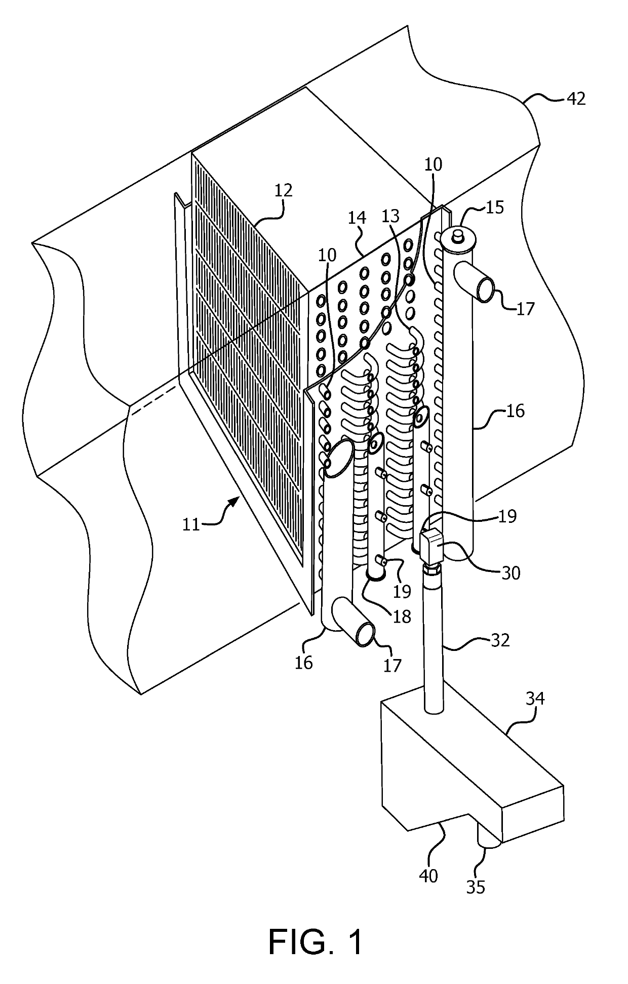
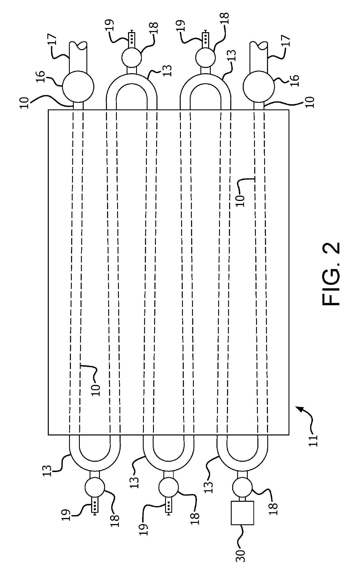
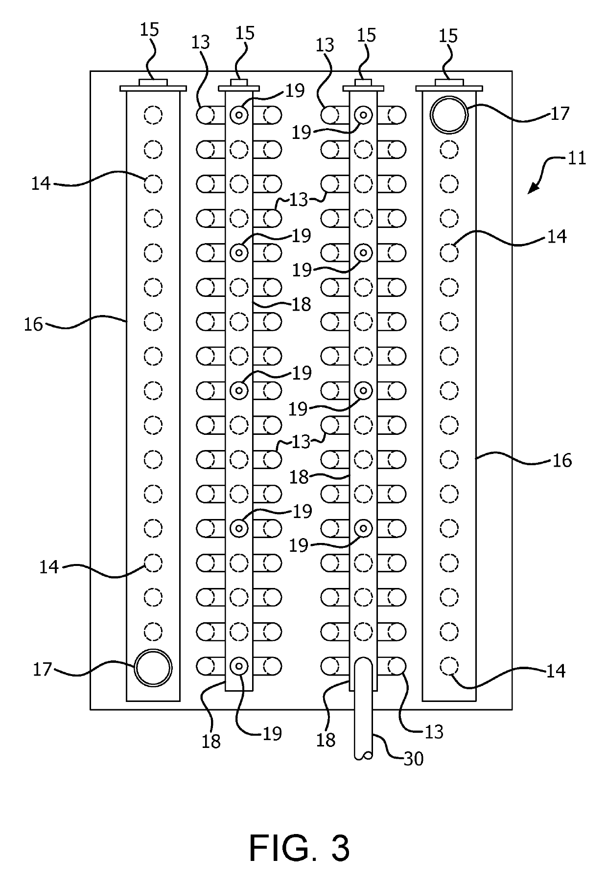
[0013]FIGS. 1-4 illustrate various views of an example embodiment of an expansion relief system utilized on an HVAC heat transfer coil of an air handler 42 in or on a building 50 (see FIG. 4), The use of the expansion relief header provides an HVAC system that is “freeze safe.” The expansion relief header enables fluid to flow out of the tubes and into an additional volume or area to accommodate fluid expansion caused by a change in fluid state (e.g., water turning to ice). The expansion relief header may also provide additional pressure relief from expansion and / or phase change of the fluid used in the tubes. The expansion relief header not only relieves pressure to protect the return bends of the fluid tubes but also allows for the resealing after expansion.

[0014]FIG. 1 illustrates a perspective view of an example expansion relief header utilized on an HVAC heat transfer coil of an air handler 42 in or on a building 50 (see FIG. 4). As illustrated, various elements of the air hand...


PUM


Abstract

A pressure and / or temperature relief header for use in an HVAC heat transfer coil includes a main body adapted to be secured to bends in fluid coils of the HVAC fluid tube system. The main body includes holes in alignment with holes formed in the bends to enable liquid to pass from the bends into the expansion relief header. The expansion relief headers include a pressure release valve that automatically opens, preferably in response to pressure exceeding a predetermined threshold value or temperature falling below a predetermined value, to release liquid from the expansion relief header and then reseats. A discharge housing collects liquid released through the pressure release valve. A sensor detects the presence of liquid in the discharge housing.

Description

RELATED APPLICATION[0001]The present application is a continuation-in-part of U.S. application Ser. No. 14 / 613,448, filed Feb. 4, 2015, which is a continuation of U.S. application Ser. No. 14 / 071,022 filed Nov. 4, 2013 and granted on Sep. 20, 2016 as U.S. Pat. No. 9,448,018, which claimed priority from U.S. Provisional Patent Application Ser. No. 61 / 727,799 filed Nov. 19, 2012, the disclosures of which are incorporated herein by reference in their entirety.FIELD OF THE INVENTION[0002]The present invention is directed to devices for use on heating, ventilating and air conditioning (HVAC) systems that reduce the risk of fluid tubes in the HVAC system from splitting when the fluid expands. In particular invention is directed to devices that allow for fluid expansion, and possibly fluid removal with the use of temperature and / or pressure relief devices.BACKGROUND OF THE INVENTION[0003]Fluid tubes are commonly used in HVAC systems, primarily in air handlers and similar cooling or heating...

Claims


Application Information

Patent Timeline
Patent Type & Authority Patents(United States)
IPC IPC(8): F28F27/00F28F9/02F28D1/047F24F140/30
CPCF28F27/00F28D1/0477F28F9/0231F28F2265/14F24F2140/30F28F2265/12
Inventor COONEY, ROBERT
Owner COONEY ROBERT
Features
  • R&D
  • Intellectual Property
  • Life Sciences
  • Materials
  • Tech Scout
  • Unparalleled Data Quality
  • Higher Quality Content
  • 60% Fewer Hallucinations
Learn More