Trial frame

a technology of frame and frame body, applied in the field of trial frames, to achieve the effect of high quality and cost-effective manufacturing

Active Publication Date: 2019-04-30
OCULUS OPTIKGERATE GMBH
View PDF21 Cites 1 Cited by
  • Summary
  • Abstract
  • Description
  • Claims
  • Application Information

AI Technical Summary

Benefits of technology

[0008]Therefore, the object of the present invention is to provide a trial frame that is of high quality and cost-effective in manufacture at the same time.

Problems solved by technology

Cumbersome demolding of the lens holder device or a potentially required rethreading of the threaded section is no longer necessary.

Method used


Image

  • Trial frame
  • Trial frame
  • Trial frame

Examples


Embodiment Construction

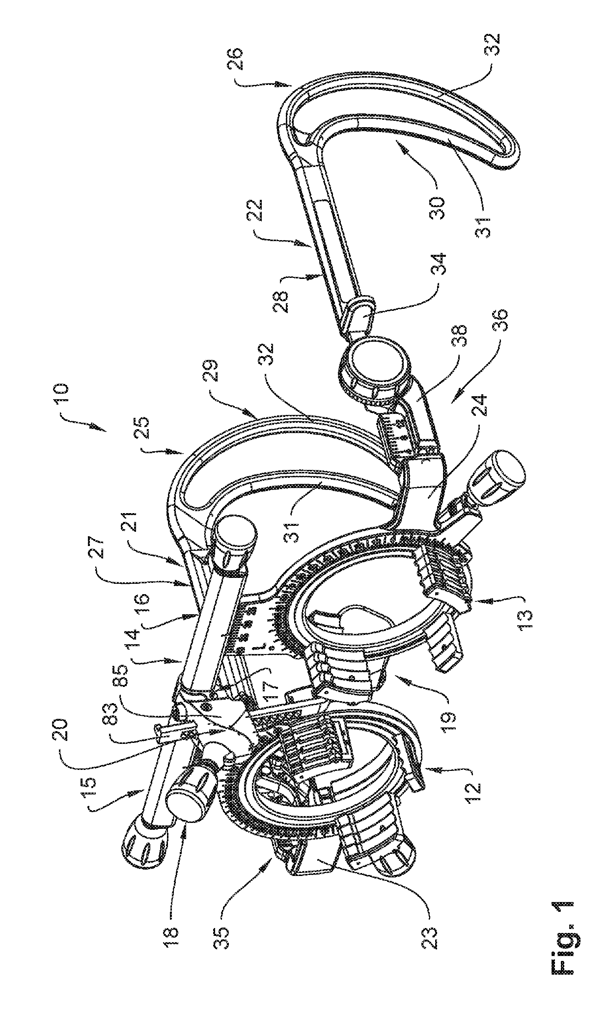
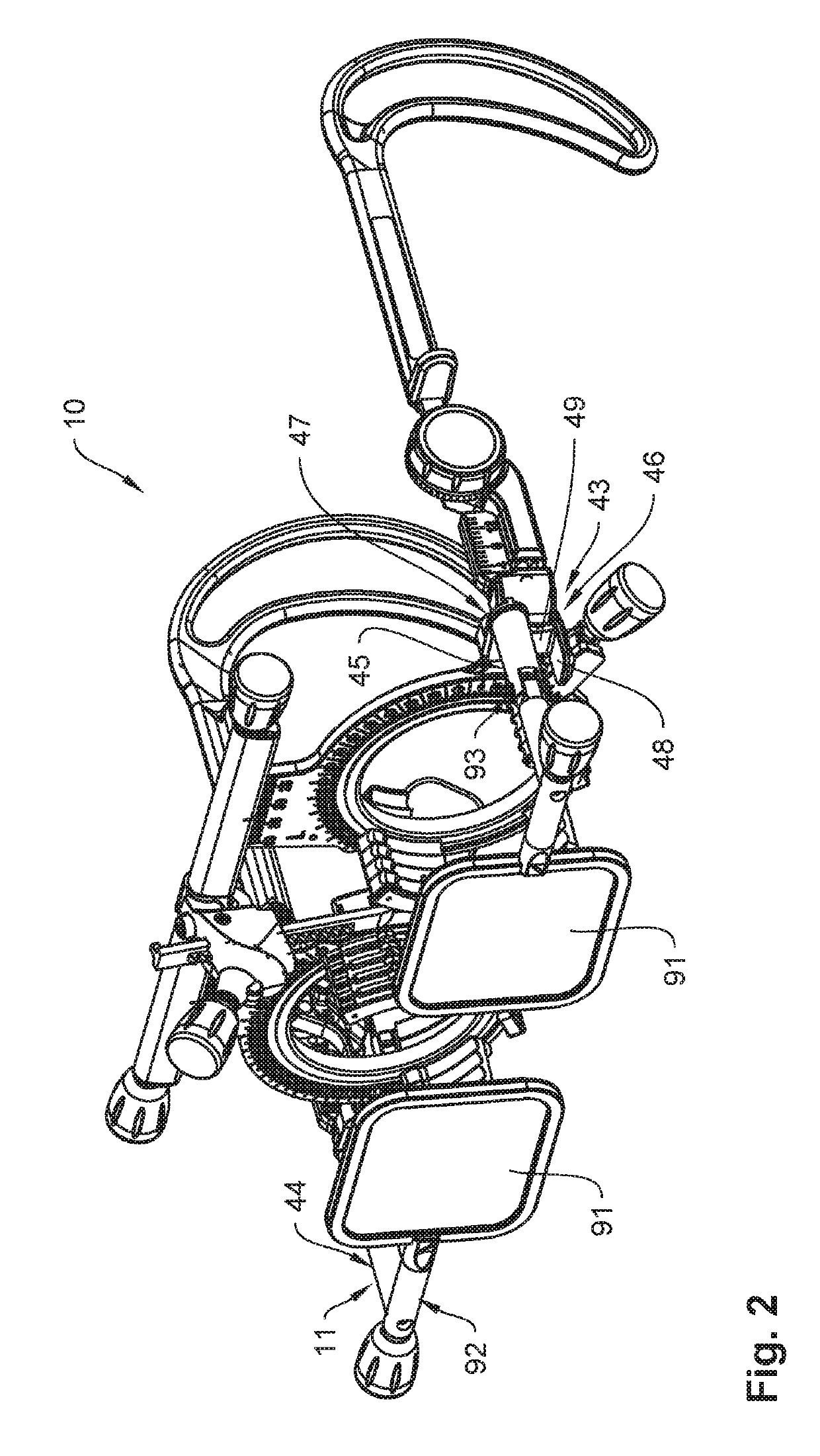
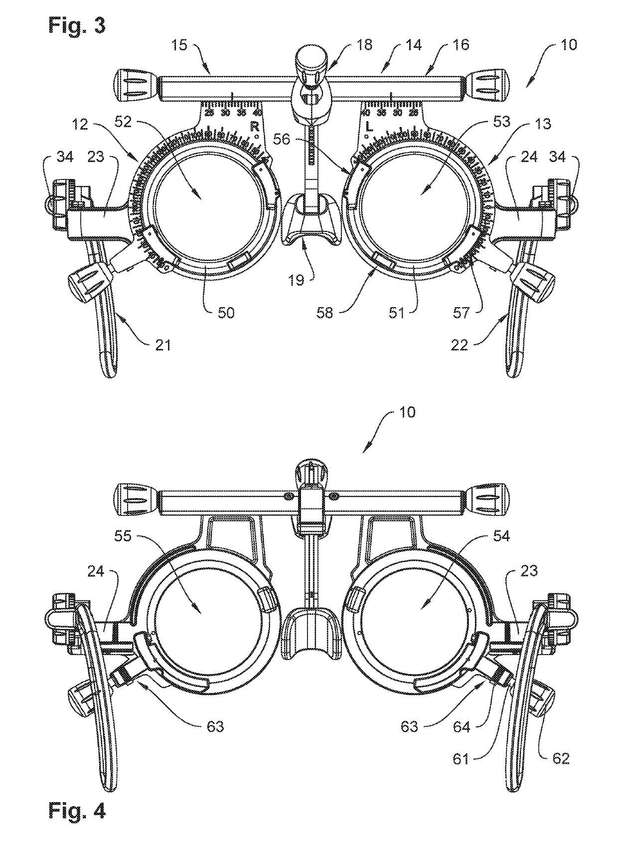
[0056]A combined view of FIGS. 1 to 7 shows a trial frame 10 in different views. In the illustrations of FIGS. 2 and 6, polarization filter devices 11 of the trial frame 10 are attached to the same. The trial frame 10 serves to determine the subjective refraction of a subject or patient (not illustrated). Hence, directional and positional terms below always relate to body planes of a subject wearing an adjusted trial frame 10. The trial frame 10 comprises two lens holder devices 12 and 13 for receiving insert lenses (not illustrated) and a bridge 14, which connects the lens holder devices 12 and 13 at a distance relative to each other in the transversal direction in an individually adjustable manner. The bridge is formed by two bridge sections 15 and 16, which are firmly connected to each other by means of a pivot axis 17. Accordingly, lens holder device 12 is adjustably attached to bridge section 15 and lens holder device 13 is adjustably attached to bridge section 16. Furthermore,...


PUM


Abstract

The invention relates to a trial frame for determining the subjective refraction of a subject, comprising two lens holder devices for receiving lenses, a bridge, which adjustably connects the lens holder devices, a nose rest device having a pivotable and height-adjustable nose rest and two temples, which are adjustable in length and height, the bridge and the lens holder devices together forming a guide means for guiding the lens holder devices in the longitudinal direction of the bridge, the bridge having a spindle gear comprising a threaded spindle for adjusting the distance of the lens holder devices, wherein at least one guide protrusion is formed on each of the lens holder devices, said guide protrusion engaging into a guide groove formed in the bridge, open threaded sections being formed on each of the lens holder devices, the threaded spindle being engaged with the threaded section.

Description

CROSS-REFERENCE TO RELATED APPLICATIONS[0001]This application claims the benefit of German Patent Application No. 10 2015 225 017.2 filed Dec. 11, 2015. The contents of which is hereby incorporated by reference as if set forth in its entirety herein.FIELD OF THE INVENTION[0002]The invention relates to a trial frame for determining the subjective refraction of a subject, comprising two lens holder devices for receiving insert lenses, a bridge, which connects the lens holder devices in such a manner that their distance relative to each other is adjustable, a nose rest device having a pivotable and height-adjustable nose rest, and two temples, which are adjustable in length and height, the bridge and the lens holder devices together forming a guide means for guiding the mobile lens holder devices in the longitudinal direction of the bridge, the bridge having a spindle gear comprising a threaded spindle for adjusting the distance of the lens holder devices.BACKGROUND OF THE INVENTION[00...

Claims


Application Information

Patent Timeline
Patent Type & Authority Patents(United States)
IPC IPC(8): A61B3/02A61B3/11A61B3/00A61B3/04G02B5/30
CPCA61B3/04A61B3/111A61B3/0075G02B5/3025G02C5/001G02C5/045G02C5/122G02C5/20
Inventor FEIERTAG, CARSTEN
Owner OCULUS OPTIKGERATE GMBH
Why Eureka
Try Eureka