
Floating image display device

a display device and image technology, applied in the field of floating image display devices, can solve the problems of person's strangeness or physiological discomfort, and the inability to place floating images,

Active Publication Date: 2019-04-30
MITSUBISHI ELECTRIC CORP
View PDF26 Cites 0 Cited by
  • Summary
  • Abstract
  • Description
  • Claims
  • Application Information

AI Technical Summary

Benefits of technology

[0008]An object of the present invention is to provide a floating image display device capable of restraining the feeling of strangeness or physiological discomfort felt by a person viewing a floating image when a person or object goes through the floating image.
[0011]According to the present invention, the feeling of strangeness or physiological discomfort felt by a person viewing the floating image can be restrained when a person or object moves through the floating image.

Problems solved by technology

However, it is undesirable to place a floating image generated by use of the plasma emission phenomenon in the vicinity of a human body.
In the floating image displayed in the air by using the technology described in Patent Document 2 or Patent Document 3, part of optical paths for forming the floating image are interrupted by a hand or body of a person moving through the floating image, and thus part of the floating image is not formed and there are cases where a person viewing the floating image (viewer or waiting person) has a feeling of strangeness or physiological discomfort.

Method used


Image

  • Floating image display device
  • Floating image display device
  • Floating image display device

Examples


first embodiment

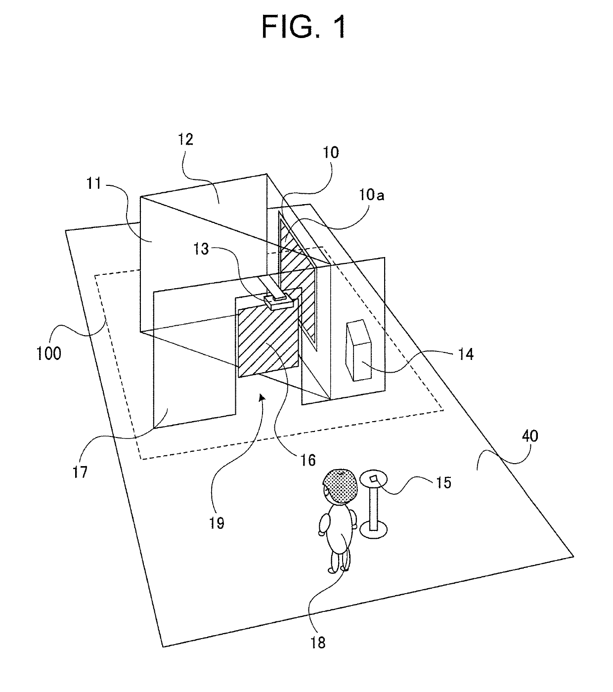
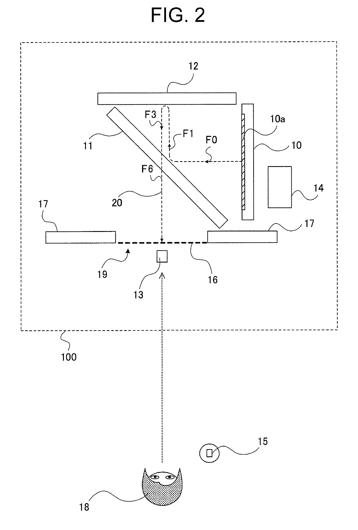
[0027]FIG. 1 is a bird's-eye view schematically showing the configuration of a floating image display device 100 according to a first embodiment of the present invention. In FIG. 1, the floating image display device 100 includes an image display unit 10, a beam splitter 11, a retroreflective sheet 12, an image projection unit 13, an image control unit 14 and an authentication unit 15. In the example shown in FIG. 1, the image display unit 10, the beam splitter 11 and the retroreflective sheet 12 are arranged so that a display surface of the image display unit 10, surfaces (a light reflection / incidence surface and a light exit surface) of the beam splitter 11 and a surface of the retroreflective sheet 12 on a retroreflecting side are substantially orthogonal to a floor surface 40 serving as a reference plane. An image (first image) displayed on the image display unit 10 is displayed as a floating image 16 at an opening part 19 of a wall 17 by a floating-image-formation optical system...


PUM


Abstract

A floating image display device includes a floating-image-formation optical system that forms an image at an opening part as a floating image from an image displayed on an image display unit, an authentication unit that judges whether or not a subject passing through the opening part is an authorized subject, and an image control unit that makes the image display unit switch contents of the image when the subject is judged as the authorized subject. The floating-image-formation optical system can include a beam splitter and a retroreflective sheet. Another floating image display device includes an image display unit that displays a first image, a floating-image-formation optical system that forms an image at an opening part as a floating image from the first image, and an image projection unit that projects a second image onto a subject moving through the floating image when the subject passes through the opening part.

Description

BACKGROUND OF THE INVENTION[0001]1. Field of the Invention[0002]The present invention relates to a floating image display device for displaying a floating image in the air where there are no display elements.[0003]2. Description of the Related Art[0004]Devices employing floating image display technology, for displaying a floating image in the air where there are no display elements, have been devised. For example, International Publication WO2014 / 041977 (Patent Document 1) discloses a device that generates a floating image by use of a plasma emission phenomenon of laser plasma and a device that uses a floating image, displayed by projecting multiple laser beams to make the beams intersect in the air, as an alternative to a wall, a partition, an entrance / crossing gate at a railway crossing or a station's ticket barrier. However, it is undesirable to place a floating image generated by use of the plasma emission phenomenon in the vicinity of a human body. Further, the method of displa...

Claims


Application Information

Patent Timeline
Patent Type & Authority Patents(United States)
IPC IPC(8): G03H1/22G03H1/00G02B27/10G02B27/14G02B27/22
CPCG03H1/2202G02B27/106G02B27/144G02B27/2221G03H1/0005G03H2240/40G03H2001/2231G03H2223/24G03H2226/05G02B30/40
Inventor SUGINOHARA, HIDETSUGU
Owner MITSUBISHI ELECTRIC CORP
Learn More