
Telescopic structure and steering column

a telescopic structure and steering column technology, applied in mechanical devices, couplings, transportation and packaging, etc., can solve the problems of low rigidity, limited rigidity, and difficulty in adjustment of rigidity, and achieve the effect of small sliding force without backlash

Active Publication Date: 2022-06-28
NSK LTD
View PDF7 Cites 0 Cited by
  • Summary
  • Abstract
  • Description
  • Claims
  • Application Information

AI Technical Summary

Benefits of technology

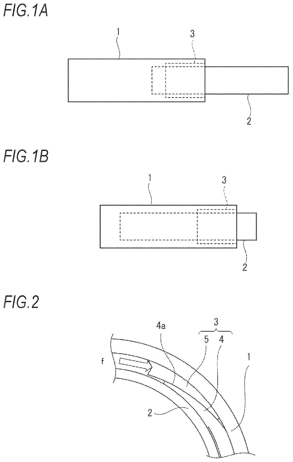
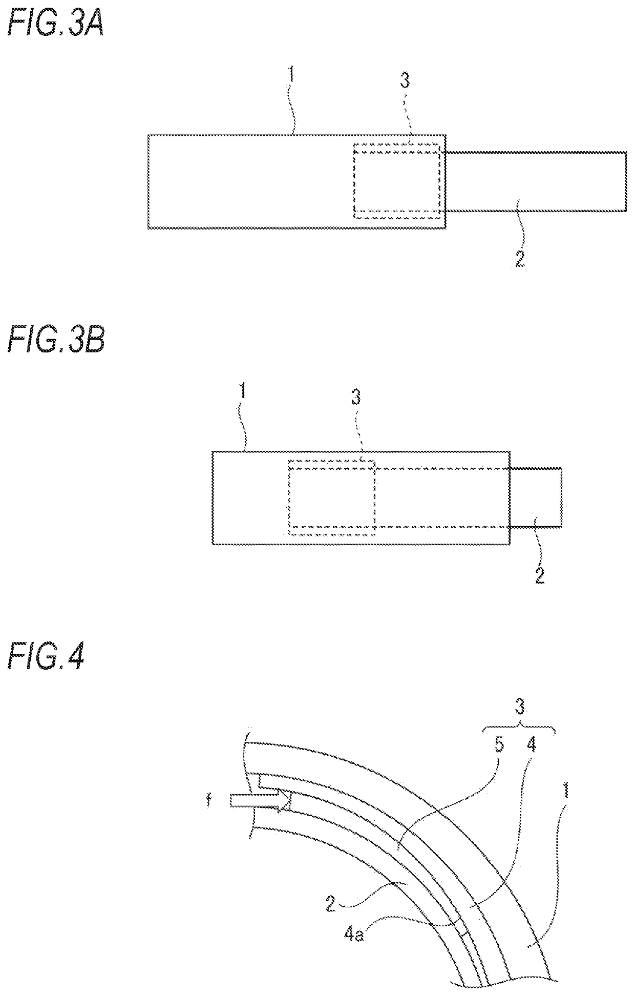
[0014]In view of the above, an object of the present invention is to provide a telescopic structure capable of realizing sliding with a small sliding force without backlash while a wedge is not affected by friction during the sliding. Another object of the present invention is to provide a steering column in which a driver does not feel a sense of discomfort such as backlash when operating a steering wheel.
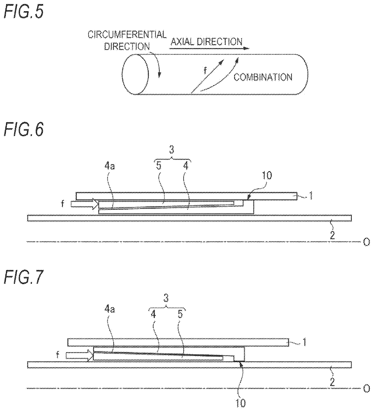
[0017]In this way, according to the present invention, the wedge biased by the biasing member deeply engages with the sleeve, and the sleeve and the wedge fill a gap between the outer tube and the inner tube, so that the sleeve and the wedge support the second tube without backlash. In particular, in the present invention, since the wedge is disposed between the first tube and the sleeve, friction does not occur between the wedge and the second tube when the second tube slides. Therefore, the wedge is not dragged and displaced from the mating surface of the sleeve when the second tube slides. Since no friction occurs between the second tube and the wedge, a sliding force is small. When the telescopic structure according to the present invention is used in a steering column, a driver can be prevented from feeling a sense of discomfort such as backlash when operating a steering wheel.
[0018]In the present invention, the wedge may have a displacement prevention structure that prevents an axial displacement from the wedge mating surface. Accordingly, the wedge can be more reliably prevented from being dragged and displaced from the mating surface of the sleeve when the second tube slides.

Problems solved by technology

In a related-art telescopic structure, radial backlash may occur in a fitting position of a plurality of cylindrical parts, resulting in low rigidity.
Disadvantages of this technology are as follows.
(In addition, the rigidity is limited by the spring force.)
The rigidity may be difficult to adjust due to this dependence.
The large sliding force increases wear and load on a motor (resulting in a slow telescope operation speed).
3. Since a contact surface of a sliding interface may not be clear, it may be difficult to control a natural frequency, the rigidity and a low-temperature sliding force.
4. A metal-on-metal contact may be a cause of increasing the sliding force, and may require the use of grease.
Due to the sliding friction between the wedge members 8, 9 and the inner surface of the outer pipe 2 when the inner pipe 4 slides, the sliding force may increase, thereby increasing wear and load on a motor (resulting in a slower telescope operation speed).

Method used


Image

  • Telescopic structure and steering column
  • Telescopic structure and steering column
  • Telescopic structure and steering column

Examples


first embodiment

[0193]FIG. 26A is an end view of a sliding interface using circumferential wedges as viewed in the axial direction according to a first embodiment of the present invention, and FIG. 26B is a partial perspective view thereof. In FIGS. 26A and 26B, the reference numeral 1 denotes an outer tube, the reference numeral 2 denotes an inner tube, a reference numeral 401 denotes a sleeve, a reference numeral 402 denotes four contact surfaces of the sleeve 401 at this axial position, reference numerals 501, 502 denote wedges, a reference numeral 601 denotes a spring, and a reference numeral 905 denotes a fixing position (fixing portion) of the sleeve. In the following description of the embodiment of the present invention, the outer tube 1 is a housing when used in the steering column described later. As shown in FIG. 26A, the sleeve 401 and two wedges 501, 502 are inserted between the outer tube (the housing) 1 and the inner tube 2. The sleeve 401 has a shape opened by a gap G on a lower sid...

second embodiment

[0195]FIG. 27A is a partial perspective view of a sliding interface using circumferential wedges according to a second embodiment of the present invention, FIG. 27B is an end view of the sliding interface in FIG. 27A as viewed in the axial direction, and FIG. 27C is a view showing an assembly of a sleeve and the wedges constituting the sliding interface in FIG. 27A. In FIGS. 27A, 27B and 27C, the reference numeral 1 denotes an outer tube, the reference numeral 2 denotes an inner tube, a reference numeral 403 denotes a sleeve, a reference numeral 404 denotes contact surfaces of the sleeve 403, reference numerals 503, 504 denote wedges, a reference numeral 603 denotes a spring, reference numerals 801, 802 denote flanges formed at both axial ends of the wedges 503, 504, and a reference numeral 906 denotes sleeve fixing protrusions (tabs). The sliding interface according to the second embodiment is different from the sliding interface according to the first embodiment in the following p...

third embodiment

[0203]FIG. 29 is an end view of a sliding interface using circumferential wedges as viewed in the axial direction according to a third embodiment of the present invention. In FIG. 29, the reference numeral 1 denotes an outer tube, the reference numeral 2 denotes an inner tube, the reference numeral 405 denotes a sleeve, reference numerals 507-1, 507-2 denote two connected wedges, and the reference numeral 605 denotes a spring. The sleeve 405 is fixed to the outer tube 1 (not shown), and covers an entire outer circumferential surface of the inner tube 2 except for a position of the gap G of the sleeve 405. Two wedges 507-1, 507-2 having wedge surfaces in the same direction and connected to each other are inserted between the outer tube 1 and the sleeve 405. An arrangement of the wedges 507-1, 507-2 in a configuration in FIG. 29 is obtained by applying the arrangement in (5) of FIG. 14 in the circumferential direction, and the sleeve 405 has two continuous portions 405-1, 405-2 having...


PUM


Abstract

An interface structure includes a sleeve, a wedge and a biasing member. The sleeve is arranged between the inner circumferential surface of the outer tube and the outer circumferential surface of the inner tube. The sleeve includes at least one fixing portion fixed to a first tube that is one of the outer tube and the inner tube, at least one contact surface configured to come into contact with a second tube that is the other of the outer tube and the inner tube, and a wedge mating surface configured to be mated with the wedge. The wedge is arranged between the first tube and the sleeve and is mated with the wedge mating surface of the sleeve. The biasing member biases the wedge so as to engage the wedge between the first tube and the sleeve while allowing the sleeve and the second tube to slide on each other.

Description

CROSS-REFERENCE TO RELATED APPLICATIONS[0001]The present application is based on U.S. Provisional Patent Application No. 62 / 951,391 filed on Dec. 20, 2019, the contents of which are incorporated herein by reference.TECHNICAL FIELD[0002]The present invention relates to a telescopic structure, and further relates to a steering column having the telescopic structure.BACKGROUND ART[0003]The telescopic structure may be provided, for example, on the steering column in a steering device of an automobile to allow a distance between a driver and a steering wheel to be adjusted. In a related-art telescopic structure, radial backlash may occur in a fitting position of a plurality of cylindrical parts, resulting in low rigidity. In order to solve this problem, for example, the following technology is disclosed.[0004]According to one technology, for example, as disclosed in FIGS. 2 and 3 of Japanese Unexamined Patent Application Publication No. 2010-083392, a member (for example, a plastic membe...

Claims


Application Information

Patent Timeline
Patent Type & Authority Patents(United States)
IPC IPC(8): B62D1/185F16D3/06F16C3/03
CPCB62D1/185F16D3/06F16C3/03
Inventor KUROKAWA, YOSHIFUMILIPA, JESSICA ELAINE
Owner NSK LTD
Learn More