
Control apparatus and control method for automatic transmission

a control apparatus and automatic transmission technology, applied in the direction of gearing control, clutches, gearing elements, etc., can solve the problems of reducing the operation amount of the brake, reducing the fuel efficiency of the engine, and not wanting the phenomenon of sudden acceleration, so as to increase the cost and prevent the driver.

Inactive Publication Date: 2006-04-27
TOYOTA JIDOSHA KK
View PDF2 Cites 0 Cited by
  • Summary
  • Abstract
  • Description
  • Claims
  • Application Information

AI Technical Summary

Benefits of technology

[0011] It is an object of the invention to provide, without an increase in cost, a control apparatus and control method for an automatic transmission, which appropriately performs control for returning from neutral control to normal control even if a state amount that is required to determine whether control should return from the neutral control to the normal control is erroneously detected, thereby preventing a driver from feeling a sense of discomfort.
[0013] With the control apparatus according to the first aspect, in a normal operation time in which the first detector that detects the braking force of the braking device is operating normally, the control returns from the neutral control to the normal control by using the first detector and the second detector. When the first detector is erroneously operating, the control returns from the neutral control to the normal control by using, for example, a brake lamp switch (the second detector) that is usually provided in the vehicle. Thus, the control can reliably return from the neutral control to the normal control. Since the brake lamp switch is used as the second detector in the above example, a fail-safe mechanism for the neutral control can be realized at low cost. As a result, it is possible to provide, without an increase in cost, the control apparatus for an automatic transmission, which appropriately performs the control for returning from the neutral control to the normal control even if the state amount that is required to determine whether the control should return from the neutral control to the normal control is erroneously detected, thereby preventing a driver from feeling a sense of discomfort.

Problems solved by technology

However, the creep phenomenon is not desired, when the vehicle needs to be kept at a standstill.
Namely, the creeping force from the engine is suppressed by the brake, causing a problem that fuel efficiency of the engine is reduced.
With this creep control apparatus for a vehicle, hysteresis of the operation amount of the brake is set when the creep prevention control is started and when the control returns from the creep prevention control to the normal control.
If the brake hydraulic pressure sensor does not operate properly, it is difficult to perform the creep prevention control (neutral control), and cause the control to return from the creep prevention control (neutral control) to the normal control.
Particularly, when the driver attempts to start the vehicle by releasing the brake pedal, timing at which the automatic transmission is shifted to the forward running state may be delayed, and the driver may feel a sense of discomfort.
If another sensor is provided in addition to the brake hydraulic pressure sensor in order to address such a problem, a production cost increases.

Method used


Image

  • Control apparatus and control method for automatic transmission
  • Control apparatus and control method for automatic transmission
  • Control apparatus and control method for automatic transmission

Examples


first modified example

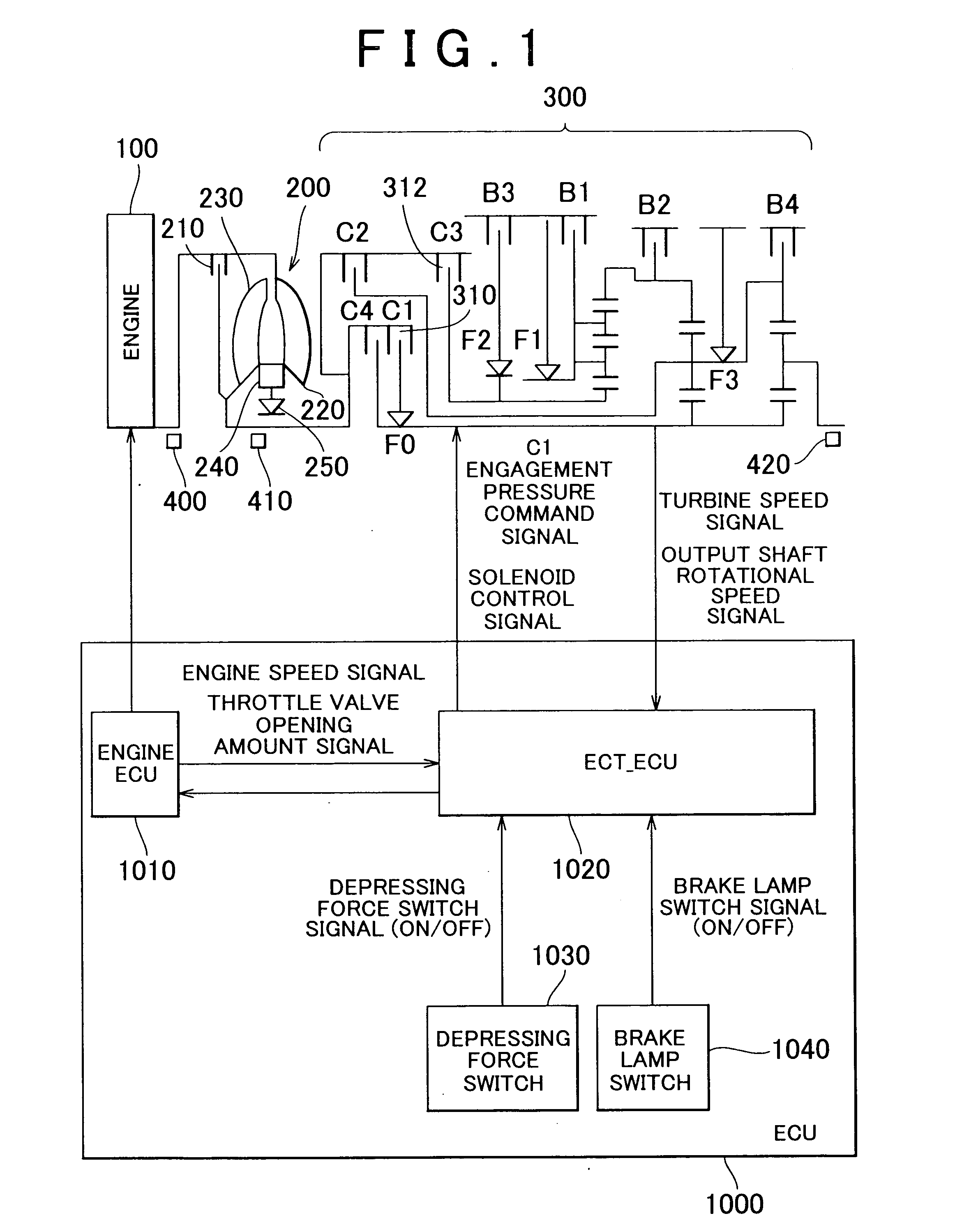
[0075] Hereafter, timing at which the control returns from the neutral control to the normal control will be described with reference to FIG. 10. In FIG. 10, the same step numbers are assigned to the same steps as those in the flowchart in FIG. 7. The processes in the steps having the same step numbers are also the same. Accordingly, the detailed description concerning the steps having the same step numbers will not be made here. Although not shown in FIG. 10, steps S200 to S220 shown in FIG. 7 are performed also in the first modified example. FIG. 10 shows the steps performed after a negative determination is made in step S200 in FIG. 7.

[0076] In step S300, the ECT_ECU 1020 determines whether the input clutch 310 has reached an engagement phase changing point. If it is determined that the input clutch 310 has reached the engagement phase changing point (“YES” in step S300), step S250 is performed. If it is determined that the input clutch 310 has not reached the engagement phase c...

second modified example

[0079] Hereafter, timing at which the control returns from the neutral control to the normal control will be described with reference to FIG. 11. In FIG. 11, the same step numbers are assigned to the same steps as those in the flowchart in FIG. 7. The processes in the steps having the same step numbers are also the same. Accordingly, the detailed description concerning the steps having the same step numbers will not be made here. Although not shown in FIG. 11, steps S200 to s220 in FIG. 7 are performed also in the second modified example. FIG. 11 shows the steps performed after a negative determination is made in step S200 in FIG. 7.

[0080] In step S400, the ECT_ECU 1020 determines whether a predetermined time has elapsed since the fact that the depressing force switch 1030 is turned OFF is detected. If the predetermined time has elapsed since the fact that the depressing force switch 1030 is turned OFF is detected (“YES” in step S400), step S250 is performed. On the other hand, if ...


PUM


Abstract

The ECT_ECU performs a step of determining that an ON failure has occurred in a depressing force switch when the depressing force switch is turned ON while a brake lamp switch is OFF, and setting a flag F; a step of determining whether the brake lamp switch, which is turned OFF at a position on a release side with respect to a depressing force switch setting position, has been turned OFF, when the flag F has been set; and a step of increasing commanded pressure for engaging an input clutch as rapidly as possible, when the brake lamp switch has been turned OFF.

Description

INCORPORATION BY REFERENCE [0001] The disclosure of Japanese Patent Application No. 2004-312696 filed on Oct. 27, 2004 including the specification, drawings and abstract is incorporated herein by reference in its entirety. BACKGROUND OF THE INVENTION [0002] 1. Field of the Invention [0003] The invention relates to a control apparatus and control method for an automatic transmission. More specifically, the invention relates to a control apparatus and control method for an automatic transmission, which performs neutral control. [0004] 2. Description of the Related Art [0005] An automatic transmission mounted in a vehicle includes a shifting mechanism which is connected to an engine via a torque converter and the like, and which includes plural power transmission paths. The automatic transmission is configured to automatically change the power transmission paths based on an accelerator pedal operation amount and a vehicle speed, namely, configured to automatically change speed ratios (...

Claims


Application Information

Patent Timeline
IPC IPC(8): B60W10/02F16H59/08F16H59/54F16H61/12F16H61/20F16H61/68F16H61/684
CPCF16H61/12F16H61/686F16H2061/1208Y10T477/75F16H2061/1284Y10T477/743F16H2061/122
Inventor KAMISHIMA, HIROFUMISAKAMOTO, TAKANORINAGAI, TADAYUKI
Owner TOYOTA JIDOSHA KK
Learn More