Molding drum

a technology of rolling drums and rolling pins, applied in the field of rolling pins, can solve the problems of limited effect and uniformity of products, and achieve the effects of reducing the length of the drum shaft, smooth expansion/contraction, and round drums

Inactive Publication Date: 2019-05-07
BRIDGESTONE CORP
View PDF31 Cites 0 Cited by
  • Summary
  • Abstract
  • Description
  • Claims
  • Application Information

AI Technical Summary

Benefits of technology

[0017]According to the invention of claim 1, the plurality of segment expansion / contraction mechanisms constituted by the plurality of swing arms is provided at intervals along the drum shaft, and expansion / contraction is performed by the plurality of segment expansion / contraction mechanisms along with movement of the slider in the drum shaft direction, and thus a plurality of rows of the swing arms can be expanded / contracted with respect to the one slider. As a result, even when the radial length of the swing arm is increased, a gap is not generated between the adjacent segments, and the tires of various sizes can be handled while roundness of the drum is maintained.
[0018]According to the invention of claim 2, since the plurality of guide members for guiding the other end portion of the swing arms in the radial direction of the drum shaft is provided on the fixing member mounted on the drum shaft, the swing arm can be smoothly expanded / contracted and at the same time, the length in the drum shaft direction can be reduced as compared with, for example, the case where a link mechanism is provided at the other end of the swing arm, and a device can be made compact.
[0019]According to the invention of claim 3, since the guide members are arranged at intervals in the drum shaft direction with respect to the fixing member, more swing arms than ever before can be smoothly expanded / contracted.
[0020]According to the invention of claim 4, since the fixing member is composed of the first and second fixing members, and in the slider outer circumferential direction, the end portions of the plurality of swing arms adjacent are guided by the first and second fixing members, respectively, expansion / contraction of the swing arm can be performed with accuracy, and a size of an entire drum can be made compact. Furthermore, expansion / contraction of many swing arms can be performed by using a simple facility.
[0021]According to the invention of claim 5, since a shaft (middle shaft) reciprocating the slider is arranged in the drum shaft, the slider can be slid with a compact configuration.

Problems solved by technology

When a gap is generated between the segments, there occurs a failure such as a defect in uniformity of a product tire or such that the tire constituent member wrapped around the drum falls into the gap.
However, in this method, in addition to an aspect of cost by preparation of a plurality of types of drums, there is generated a work of changing the drum each time the tire size is changed, which becomes a hindrance factor of productivity enhancement in molding of the tire constituent member.
However, a drum configuration of Patent Literature 1 can be applied only to molding of two tires each having different inner diameter, and its effect is limited.

Method used


Image

  • Molding drum
  • Molding drum
  • Molding drum

Examples


Embodiment Construction

[0027]Next, an embodiment of the present invention will be described by referring to the attached drawings.

[0028]FIG. 1 is a view schematically illustrating a tire molding device provided with a drum according to the embodiment of the present invention.

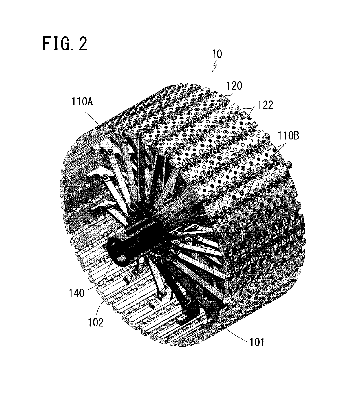
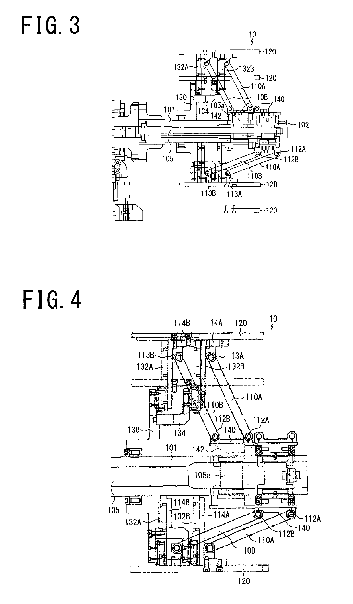
[0029]The tire molding device includes, as schematically illustrated in FIG. 1, a drum 10 and a rotating mechanism 20 rotating the drum 10, a middle-shaft driving mechanism 30 for reciprocating a middle shaft 105 (FIG. 3) which is arranged concentrically in a rotating shaft 101 of the drum 10 (hereinafter referred to as a drum shaft) and will be described later, and a supporting portion 40 for supporting an entirety on a floor surface G.

[0030]Here, the rotating mechanism 20 is arbitrary as long as the mechanism can rotate and drive the drum 10 and is a known mechanism such as a mechanism for transmitting rotation of a driving motor to a drum shaft 101. Furthermore, a known linear motion mechanism such as a cylinder mechanism or a scre...


PUM

PropertyMeasurementUnit
distanceaaaaaaaaaa
inner diameteraaaaaaaaaa
sizeaaaaaaaaaa

Abstract

Even when a radial length of a swing arm is increased, no gap is generated between adjacent segments, and tires of various sizes can be handled while roundness of a drum is maintained. An expandable molding drum has a plurality of segments constituting a circumferential surface, the molding drum having a plurality of swing arms having one end portion swingably connected to an outer circumferential surface of a cylindrical slider externally fitted with a drum shaft and having the other end portion swingably connected to the segment and expanding / contracting the segment along with movement of the slider in a drum shaft direction, and adjacent end portions of one end portions of the swing arms being swingably connected to the outer circumferential surface of the slider at intervals from each other in the drum shaft direction.

Description

TECHNICAL FIELD[0001]The present invention relates to a molding drum capable of expansion / contraction (expandable molding drum), for example, a tire molding drum, or particularly to a molding drum in which an expansion / contraction stroke in expansion / contraction can be set longer than that of a prior-art molding drum.BACKGROUND ART[0002]As a molding drum, for example, a tire molding drum (in the following description, referred to simply as a drum), there is known a drum in which its circumferential surface is constituted by a plurality of segments which is divided, each segment is mounted at a tip end of a plurality of expandable arms radially extending from a center axis of the drum, and a tire constituent member is molded so that a gap is not generated between the segments when the arm is extended.[0003]When such a drum is used, there is no problem as long as an inner diameter of a tire to be molded has such a size that a gap is not generated between the segments, but a gap is nat...

Claims


Application Information

Patent Timeline
Patent Type & Authority Patents(United States)
IPC IPC(8): B29D30/26B29D30/24
CPCB29D30/26B29D30/242B29D30/245B29D2030/2657B29D2030/2642
Inventor IYANAGI, SATOSHI
Owner BRIDGESTONE CORP
Why Eureka
Try Eureka