Cylinder block structure

a technology of cylinder block and structure, which is applied in the direction of cylinders, casings, machines/engines, etc., can solve the problems of increasing the weight of the whole cylinder block and the inability to efficiently perform casting operation of the cylinder block

Active Publication Date: 2006-07-18
NISSAN MOTOR CO LTD
View PDF8 Cites 1 Cited by
  • Summary
  • Abstract
  • Description
  • Claims
  • Application Information

AI Technical Summary

Benefits of technology

[0007]According to the present invention, the upper parts of the coupling surface at the rear end of the cylinder block are joined by the arch-shaped rib into an arch-shape; the lower ends of the right and left bolt hole bosses having bolt holes formed therein extend to the lower parts of the arch-shaped rib and are joined to the arch-like rib; and the right and left main radial ribs extend from outside of the lower ends of the right and left bolt hole bosses toward the center of the crankshaft bearing portion. Therefore, when the cylinder head is coupled onto the cylinder block with bolts, although a force may act to generate a falling deformation of the bolt hole boss, the cylinder block is pulled up to the side of the cylinder head and the tightening force of the bolt is dispersed excellently in the directions of the arch-shaped rib and main radial rib. Thus, the deformations of the cylinder and crank bearing portion are minimized, so that the roundness of the crank bearing portion is secured, thereby eliminating seizure of the crank bearing portion, sealing failure and so on.
[0011]Because the horizontal reinforcement rib for connecting the right and left main radial ribs is provided, stiffness of the right and left main radial ribs is enhanced by the horizontal reinforcement rib, so that the number of the ribs on the cylinder head rear end surface can be minimized, thereby securing light weight cylinder head having an excellent castability.

Problems solved by technology

In the above-described current structure where a number of ribs are formed in vertical and radial directions, there have been problems that the weight of the whole cylinder block increases and that the casting operation of the cylinder block cannot be efficiently performed.

Method used


Image

  • Cylinder block structure
  • Cylinder block structure
  • Cylinder block structure

Examples


Embodiment Construction

[0015]Hereinafter, the preferred embodiments of the present invention will be described with reference to the accompanying drawings.

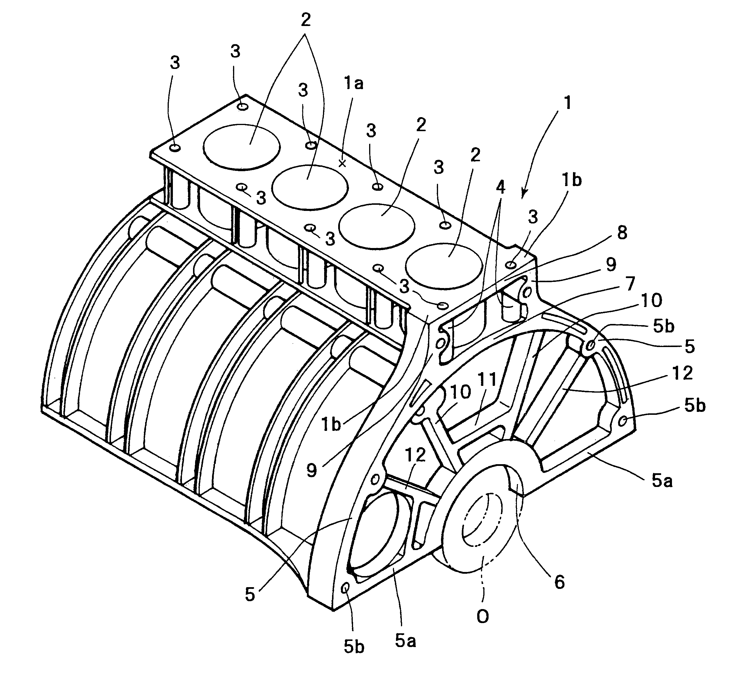
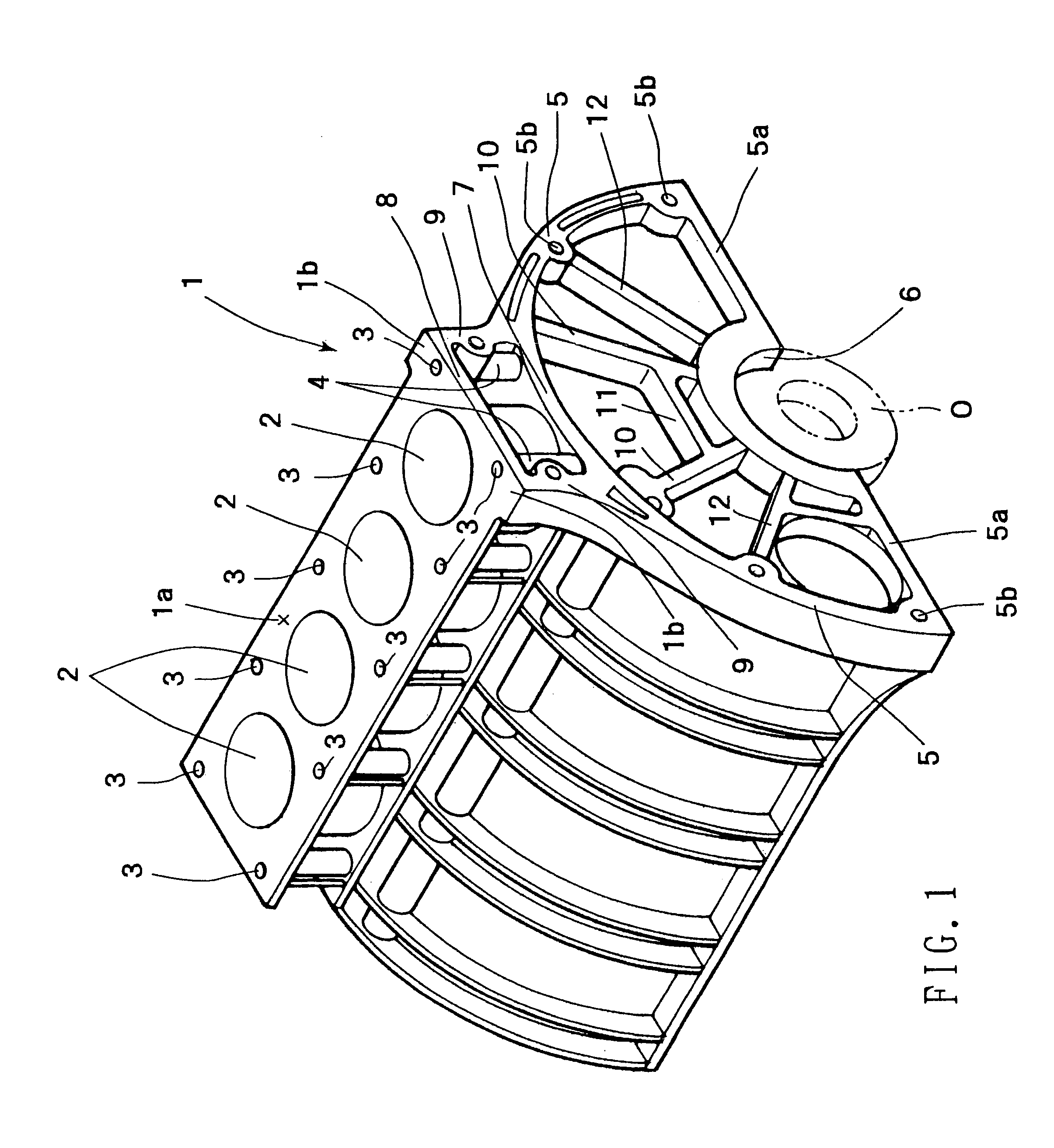
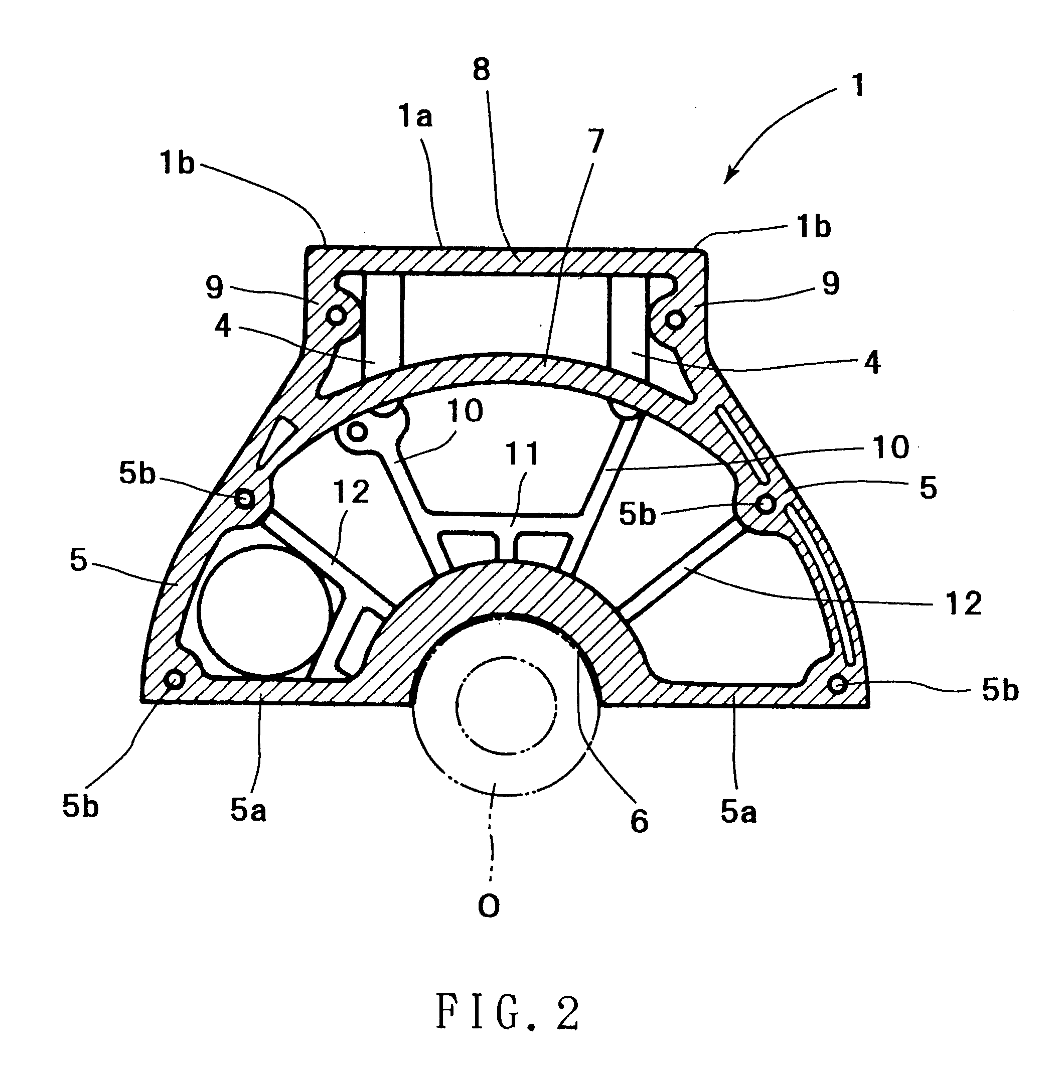
[0016]FIG. 1 is a perspective view of the cylinder block and FIG. 2 is a side view of the rear end portion of the cylinder block.

[0017]A cylinder head mounting face 1a on which the cylinder head is to be mounted is formed on the upper surface of the cylinder block 1. Four cylinder bores 2 are formed in the cylinder block 1 to extend vertically such that they are open at the upper surface of the cylinder block 1. A plurality of bolt holes 3 are formed at intervals in the cylinder block 1 and are positioned outside of the cylinder bores.

[0018]Bolts are inserted from above into bolt holes 3 and are tightened, so that the cylinder head is mounted on the upper surface.

[0019]Right / left flange-shaped reinforcement portions 1b extending outward are formed integrally with both right and left sides of the rear end of the cylinder head mounting face 1a. A top face...


PUM


Abstract

A cylinder block structure with a small number of ribs is provided which can favorably prevent the deformation of a crankshaft bearing portion. In a cylinder block having bolt holes formed on the upper surface for connecting a cylinder head with bolts, arcshaped coupling surfaces formed on the rear end surface for mounting a housing, such as a transmission housing, and a crankshaft bearing portion formed in the central part between the lower ends of the coupling surfaces, the upper parts of the coupling surfaces 5 are joined into an arch-shape by an arch-shaped rib, the lower ends of right and left bosses are extended and connected to the lower parts of the arch-shaped rib, and right and left main radial ribs extend from the outside of the lower end of the bolt hole boss to the center of the crankshaft bearing portion.

Description

FIELD OF THE INVENTION[0001]The present invention relates to a structure of a cylinder block and more particularly to a structure of a cylinder block rear end on which a housing, such as a transmission housing, may be mounted.BACKGROUND OF THE INVENTION[0002]In a case of the prior art, as disclosed in the following patent document, a number of ribs are formed in vertical and radial directions in the region of a joining surface at the rear end of a cylinder block on which a transmission case is mounted.[0003]Unexamined Patent Publication No. H10-205389[0004]In the above-described current structure where a number of ribs are formed in vertical and radial directions, there have been problems that the weight of the whole cylinder block increases and that the casting operation of the cylinder block cannot be efficiently performed.[0005]In views of the above-described problems of the prior art, it is an object of the present invention to provide a cylinder block that can minimize the numb...

Claims


Application Information

Patent Timeline
Patent Type & Authority Patents(United States)
IPC IPC(8): F02F7/00F02F1/00
CPCF02F7/00F02F7/0068F02F7/0007
Inventor HADA, MASATOSHIMURATA, SATOSHISATOU, NAOYUKI
Owner NISSAN MOTOR CO LTD
Why Eureka
Try Eureka