
Parallel tensioning device for glass filament tube
A tensioning device and glass fiber technology, applied in textiles and papermaking, etc., can solve problems such as difficulty in ensuring manufacturing accuracy and small round jumps in the original silk tube, and achieve a wide range of tensioning diameters, large bonding surfaces, and large torques. Effect
- Summary
- Abstract
- Description
- Claims
- Application Information
AI Technical Summary
Problems solved by technology
Method used
Image

Examples
Embodiment Construction
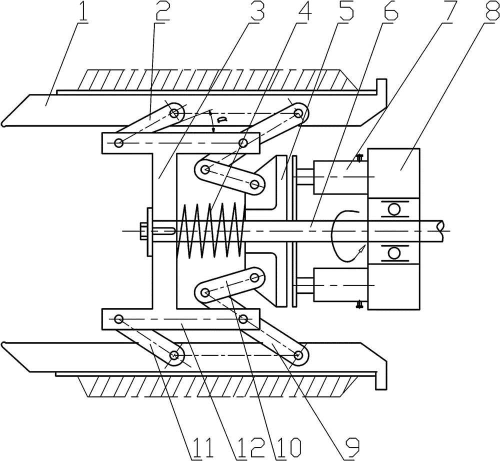
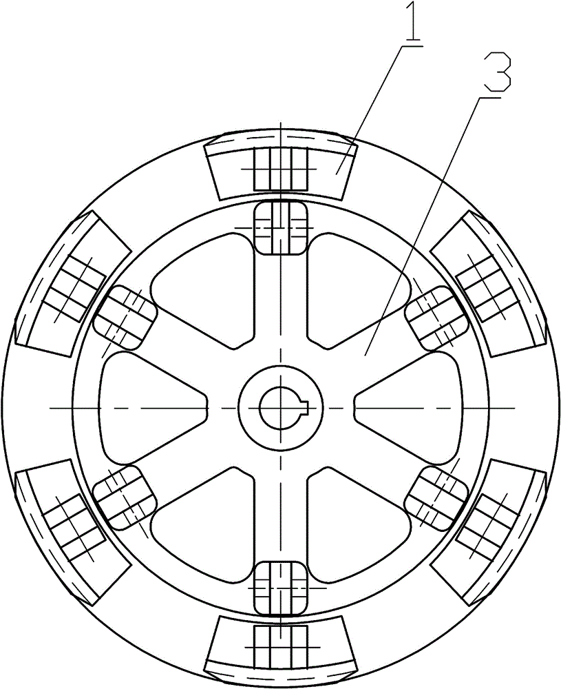
[0017] like figure 1 , figure 2 Among them, a parallel tensioning device for a glass filament tube, including a blade 1, a plurality of blades 1 distributed on the circumference are hinged to a connecting rod support 3 through a double-row linkage mechanism 2, and the connecting rod support 3 is connected to a central shaft 6 connection, the connecting rod sliding sleeve 5 can be slidably installed on the central shaft 6 along the central shaft 6, and the connecting rod sliding sleeve 5 is connected with the double-row linkage mechanism 2; the central shaft 6 is directly driven by the motor to rotate, or by A gear drive or a belt drive drive drives the rotation.
[0018] In an optimized solution, the number of blades 1 is 6. 6 blades are evenly distributed on the circumference.
[0019] A side of the connecting rod sliding sleeve 5 away from the connecting rod sliding sleeve 5 is provided with a plurality of cylinders 7 for driving the connecting rod sliding sleeve 5 to sl...
PUM
 Abstract
Description
Claims
Application Information