A pipe bending mechanism of a thin-walled short u-bend automatic forming machine

An automatic forming machine and pipe bending technology, which is applied to metal processing equipment, feeding devices, positioning devices, etc., can solve the problems of difficult multi-point clamping, limited clamping and positioning area, poor forming accuracy, etc., to simplify production equipment. The effect of structure, reducing equipment cost and long service life

Active Publication Date: 2018-01-30
TONGLU QIANDING TECH
View PDF9 Cites 0 Cited by
  • Summary
  • Abstract
  • Description
  • Claims
  • Application Information

AI Technical Summary

Problems solved by technology

[0003] Thin-walled short U-bends with welding rings on the market basically adopt manual or semi-automatic operation methods, whether it is the elbow forming process or the sleeve welding ring process. In actual production, there are labor-intensive, low-efficiency, and poor forming accuracy. And other issues
[0004] In order to solve this problem in the bending pipe forming process, in the Chinese Patent Publication No. CN104826925A, Zhangjiagang Jiangsu University of Science and Technology Industrial Technology Research Institute and Jiangsu University of Science and Technology jointly disclose a bending forming production line, which includes an unwinding mechanism and a feeding straightening device , cutting mechanism, bending forming equipment and feeding mechanism, wherein the bending forming equipment clamps the pipe material through the central clamping device, and the left and right double heads are individually bent. Although the left and right bending forming devices are equipped with clamping devices, the pipe can be It plays a role in positioning during the material bending process, but for the forming of thin-walled short U-bends, except for the straight pipe sections at both ends, the middle part needs to be bent and deformed, which also means that the clamping and positioning area is limited during the bending process , it is not easy to clamp at multiple points. If this scheme is used for thin-walled short U-bend processing, wrinkles will occur on the U-shaped arc surface of the pipe material, and the inner diameter of the pipe material clamping point will shrink, which will affect the flow rate and service life of the pipe material.

Method used


Image

  • A pipe bending mechanism of a thin-walled short u-bend automatic forming machine
  • A pipe bending mechanism of a thin-walled short u-bend automatic forming machine
  • A pipe bending mechanism of a thin-walled short u-bend automatic forming machine

Examples


Embodiment Construction

[0034] The present invention will be further described below, but the present invention is not limited to the following examples.

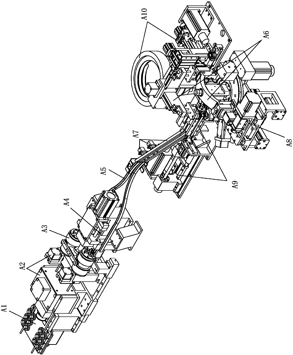
[0035] figure 1 Shown is an automatic thin-wall short U-bend pipe forming machine with welding ring, including: a feeding assembly with a pipe straightening machine A1 and a clamping mechanism A2, through which the pipe is clamped and fed forward; A pipe cutting assembly with a cutter mechanism A3 and a pipe cutting mandrel mechanism A4, through the action of the cutter mechanism and the pipe cutting mandrel mechanism, the pipe is cut into a fixed-length pipe; one has a linear vibrating feeder A5 and an intermittent feeder A7 material transfer assembly sends the fixed-length pipes to the pipe bending mechanism one by one; a pipe bending mechanism A9 bends the fixed-length pipes into a U shape; a circle indexing assembly A6 turns the pipes bent into a U shape To the shaping assembly A8 and the sleeve welding ring A10 assembly.

[0036] Such as ...


PUM


Abstract

The invention relates to the technical field of automatic equipment, and discloses a pipe bending mechanism for an automatic thin-wall short U-shaped bent pipe forming machine. Bent pipe forming at the middle part of a thin-wall short U-shaped bent pipe can be finished, material waste can be effectively reduced, wrinkling of the pipe wall is avoided, the product quality and the service life are guaranteed, and the beneficial effects that the work efficiency is high, and the automation degree is high should be achieved. According to the adopted technical scheme, the pipe bending mechanism for the automatic thin-wall short U-shaped bent pipe forming machine is characterized by comprising at least one fixed part, a semicircle die, a movable part and a third drive mechanism, one end of a fixed-length pipe is clamped at the fixed part, after crossing the semicircle die, the other end of the fixed-length pipe is in movable fit to the movable part, the movable part is driven to swing through the third drive mechanism, a middle section of the fixed-length pipe is bent around the semicircle die to form an arc section, and the thin-wall short U-shaped bent pipe is formed.

Description

technical field [0001] The invention relates to the technical field of automation equipment, in particular to a pipe bending mechanism used for bending U-bends on a thin-walled short U-bend automatic forming machine. Background technique [0002] With the continuous advancement of science and technology and the rapid development of industrial production, the demand for bent pipes in industry is gradually increasing. The quality of bent pipes will directly affect the structural rationality, safety and reliability of products in these industries. sex. The thin-walled short U-bend tube with welding ring is an important part of the heat exchanger and is widely used in heat exchangers, air conditioners, refrigerators and other equipment. [0003] Thin-walled short U-bends with welding rings on the market basically adopt manual or semi-automatic operation methods, whether it is the elbow forming process or the sleeve welding ring process. In actual production, there are labor-int...

Claims


Application Information

Patent Timeline
Patent Type & Authority Patents(China)
IPC IPC(8): B21D9/05B21D9/04B21D43/00
CPCB21D9/04B21D9/05B21D43/003
Inventor 潘炎忠
Owner TONGLU QIANDING TECH
Why Eureka
Try Eureka