Lamp cap with build-in switch and LED tube

a technology of led tube and switch cap, which is applied in the direction of lighting device details, light sources, lighting and heating apparatus, etc., can solve the problem of risk of insertion of led tube into the pin cap immediately, and achieve the effect of high precision control, cheap cost and pleasing design

Active Publication Date: 2019-05-14
CH LIGHTING CO LTD
View PDF2 Cites 0 Cited by
  • Summary
  • Abstract
  • Description
  • Claims
  • Application Information

AI Technical Summary

Benefits of technology

[0007]Aiming at the problems existing in the present technology, present invention provides a built-in switch cap and LED tube. The micro switch installed in the cap will be pressed when tube is inserted to the lamp holder, then the power source starts to work and light up the LED tube. It can replace existing lamp cap with safety and better commonality.
[0009]The present invention improves from existing lamp cap and uses micro switch technology which enables lamp to connect directly to certain voltage power. With advantages of its small volume, pleasing design and cheap cost, such cap could be widely applied with convenience, and enables connection with power source by micro switch.
[0011]The present invention could use integrated lamp cap, or combination cap. As for preferred option, the other end of the cylinder body is sealed by end closure wherein pins are inserted, and on the end closure, a through hole is installed for cooperation of the extrusion of the press-button. Therefore, the lamp cap, formed by the cylinder body and the end closure, makes whole tube assembly simple. The end closure could be bonded or bolted to be fixed inside of the cylinder body. The press-button extends outwards through the through hole, and will be pressed inwards when receiving resistance from the lamp holder.
[0013]Preferably, a limiting board is installed on the press-button for preventing the press-button from slipping from the cylinder body, the limiting board is slightly larger than the through hole, with one surface of the limiting board has bumping points to trigger the micro switch, and the surface of the limiting board also has a steering bar.
[0021]The present invention adopts micro switch technology to achieve highly precise control, with advantage on its small volume, pleasing design and cheap cost, such cap could be widely applied with convenience, and enables driver powered by micro switch.

Problems solved by technology

If the switch is open, there exists some risk of inserting the LED tube to the pin cap immediately.

Method used


Image

  • Lamp cap with build-in switch and LED tube
  • Lamp cap with build-in switch and LED tube
  • Lamp cap with build-in switch and LED tube

Examples


Embodiment Construction

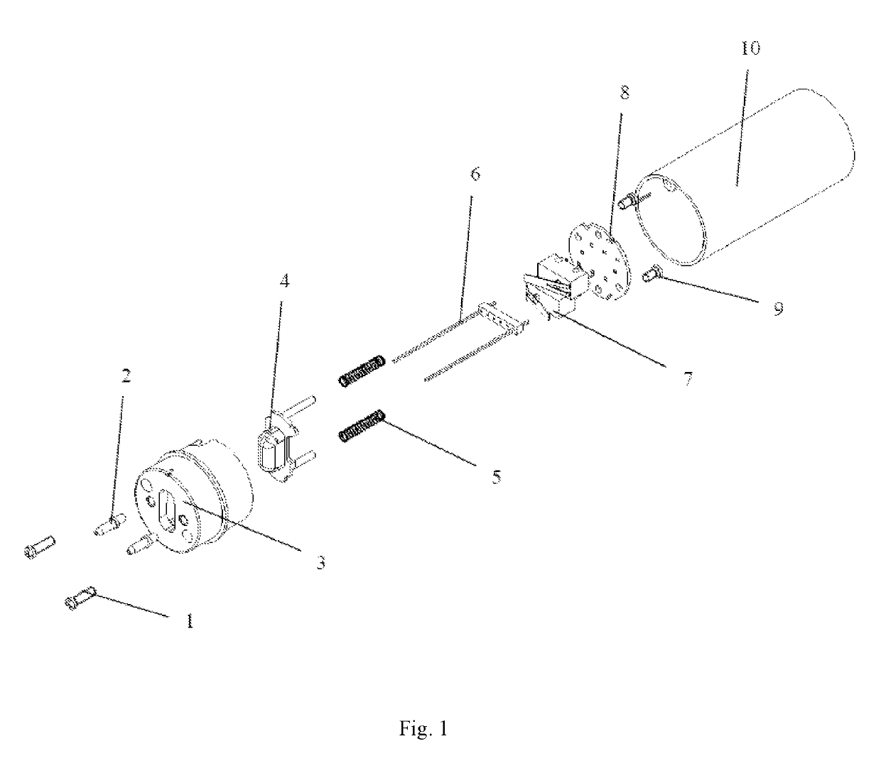
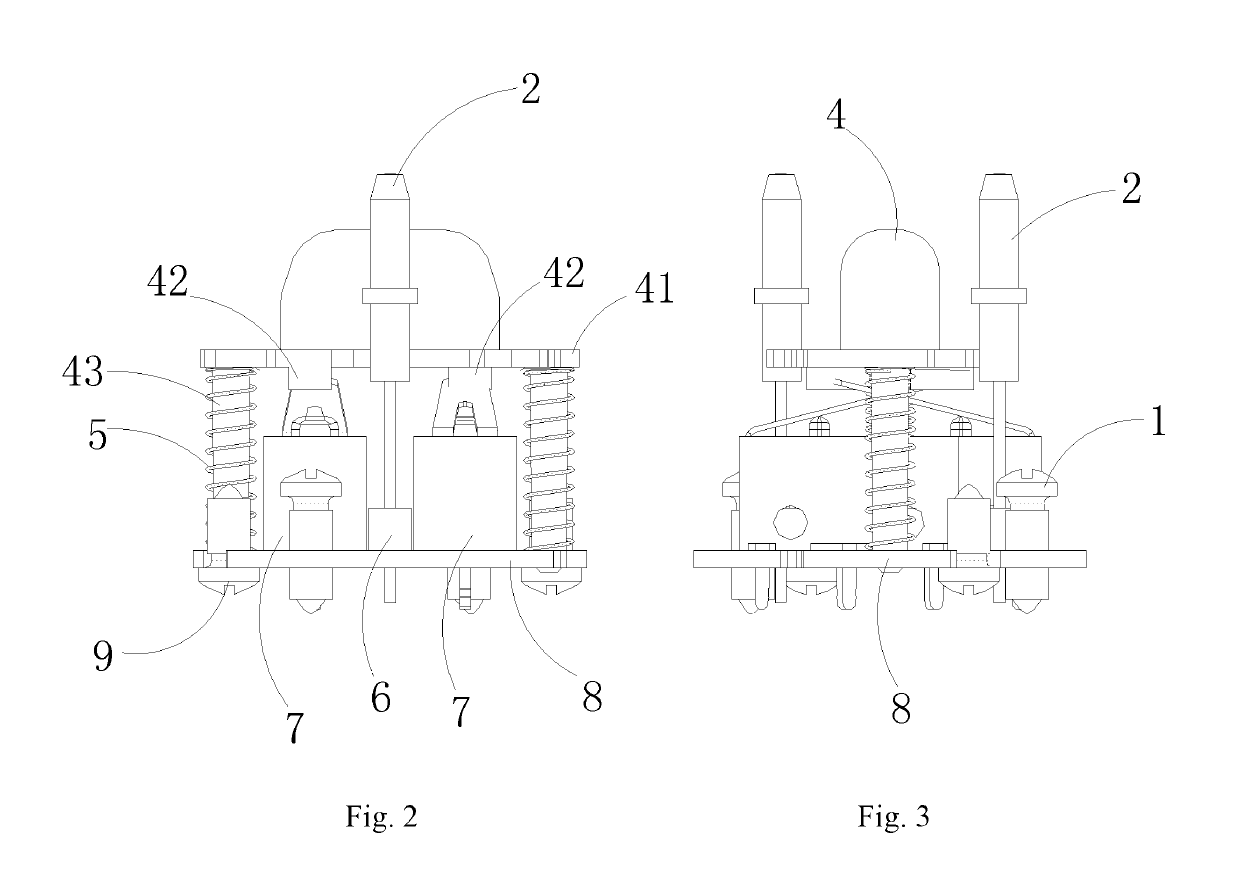
[0027]The lamp cap as shown in FIGS. 1˜5, including an end closure 3, a cylinder body 10, pins 2, a press button 4, a spring 5, a row pin 6, a micro switch 7 and a printed circuit board 8, a pin 6, a spring 5, a micro switch 7 and a printed circuit board 8 are all set inside of the lamp cap, wherein the printed circuit board 8 and the micro switch 7, the row pin 6, and the pin 2 are electrically connected to the power source (not shown) of the lamp.

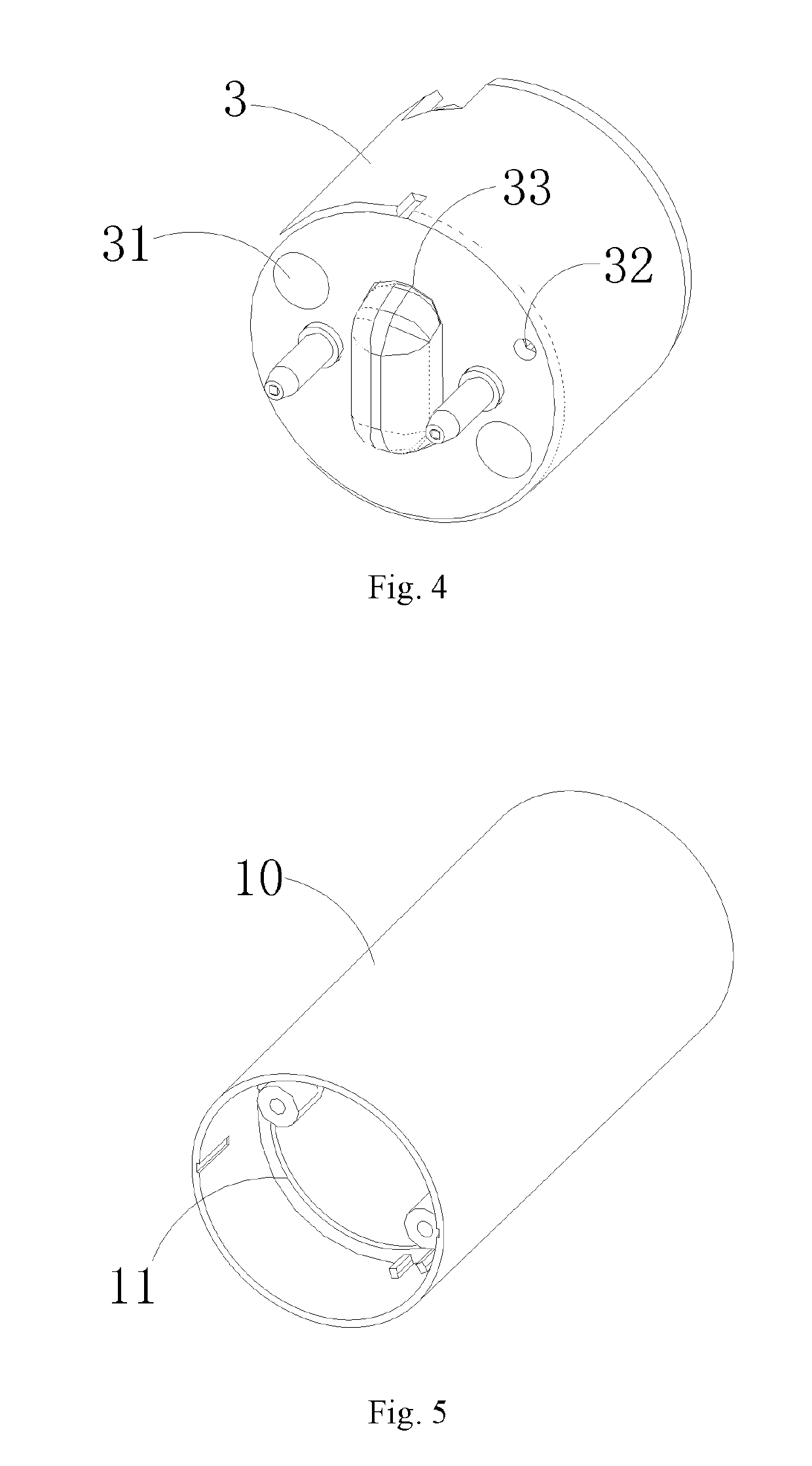
[0028]The two ends of the cylinder body 10 are open, wherein one end is used to assembly the tube, the end closure 3 is inserted into the other end of the cylinder body 10 to sealingly close that end. The inner wall of the cylinder body 10 is provided with the rim 11 for position limiting purposes, the end closure 3 is inserted in the cylinder 10 and engages against the rim 11, which can control the position of the end closure. The rim 11 is provided with bolt holes to fix the end closure 3. After the end closure 3 is assembled into the c...


PUM


Abstract

The invention discloses a built-in switch cap, including a cylinder body, one end of which is open for setting a tube, the other end is closed and is provided with pins and connected with a drive power. There is a micro-switch installed in the cap to control the ON / OFF of the drive power; a flexible button is provided to press the above micro switch, the press button is bulging from on the closed side of the cylinder body. The invention discloses a LED tube, which at least has one cap. The invention uses the micro switch installed in the lamp cap, pressing the button on the cap when touching the switch, the power source supplies power, increasing the safety of products. The cap also can directly replace the existing cap, with a strong commonality.

Description

[0001]The present application claims the priority benefit of Chinese Application No. 201610738655.8, filed Aug. 8, 2016, which is hereby incorporated by reference.TECHNICAL FIELD[0002]The present invention relates to the field of LED (light-emitting diode) lighting, specifically involving a built-in switch cap and LED tube.BACKGROUND TECHNOLOGY[0003]LED tube is also known as clean tube and fluorescent tube, with the LED as an illuminant body. A LED using light emitting diode as its light source, which has higher light efficiency, more energy saving, longer lifetime and environment-friendly, has become the most ideal product to replace fluorescent lamp. A LED tube has the same exterior dimension and tube diameter as fluorescent tube, such as T5 tubes, T8 tubes and T10 tubes, and so on.[0004]A LED tube has a very simple way of installation including removing the original tube, then inserting the pin cap on both ends of the LED tube into the lamp holder, directly adding the AC to two e...

Claims


Application Information

Patent Timeline
Patent Type & Authority Patents(United States)
IPC IPC(8): F21K9/272F21V25/04F21V23/04F21V19/00F21K9/275F21K9/278F21Y103/10
CPCF21K9/272F21V23/04F21V25/04F21Y2103/10F21K9/278F21V19/0005F21K9/275
Inventor ZHAO, GUOSONGSU, JIANHUA
Owner CH LIGHTING CO LTD
Why Eureka
Try Eureka