Toilet flange that can be rotated during insertion having a gripping ring and a durable safety seal

a technology of safety seal and toilet flange, which is applied in the field of toilet flanges, can solve the problems of damage to the structure of the dwelling, unsatisfactory odor, etc., and achieve the effects of reducing the number of leaks, and being easy to install

Active Publication Date: 2019-05-21
CONNELL DARRELL GREGORY
View PDF32 Cites 0 Cited by
  • Summary
  • Abstract
  • Description
  • Claims
  • Application Information

AI Technical Summary

Benefits of technology

[0018]The toilet flange of the invention addresses many of the shortcomings of traditional closet flanges. The toilet flange of the invention is simpler and faster to install than a traditional toilet flange. The toilet flange of the invention provides a longer lasting seal than a traditional toilet flange. Providing a longer lasting seal reduces the number of leaks from a broken toilet seal. This is a major advantage, since a toilet flange leak can release unsanitary or toxic fluids and gases, such as sewer gases, into the dwelling. A toilet flange leak can spread disease, can cause unpleasant odors, and can damage the structure of the dwelling by staining the walls, ceilings, and floors, damaging plaster and drywall, and by contaminating many of the building's structural components so that they must be cleaned or replaced. The toilet flange of the invention minimizes such leaks, when compared to traditional toilet flanges.
[0019]The toilet flange of the invention has an embodiment that is inserted into the inside of the top portion of a drain pipe. This embodiment includes a circumferential gripping ring which is rotatably seated within a circumferential channel that is along the outside of the pipe portion of the toilet flange. The circumferential gripping ring in cooperation with the circumferential channel provides a one-way, irreversible insertion into the inside of the top portion of the toilet drain. The circumferential gripping ring also cooperates with the circumferential channel to provide convenient rotational adjustment of the toilet flange with respect to the drain pipe. This means the plumber can easily change the rotational angle of the toilet flange once it is inserted into the drain pipe, which facilitates lining up the bolts on the toilet flange with the bolt holes on the toilet. Therefore the rotational angle of the toilet flange can be quickly modified without unscrewing any screws, and without regluing any joints, for a faster, simpler, and less costly toilet installation.
[0020]The embodiment that is inserted into the inside of the top portion of a drain pipe also has a circumferential groove disposed along the outside of the pipe portion of the toilet flange, which seats a side sealing ring which makes a seal with the inside of the drain pipe. This side sealing ring prevents unsanitary or toxic fluids or gases from the sewage system from rising above the side sealing ring of the toilet flange and entering the residence. For drain pipes with a rough internal surface, the side sealing ring can be replaced by a side sealing gasket, which has a larger contact sealing area. For embodiments where the side sealing ring is located below the circumferential gripping ring, the side sealing ring also protects the circumferential gripping ring from sewage fluids or gases. This minimizes corrosion of the circumferential gripping ring and prevents dirt, liquids, and debris from interfering with the gripping action of the circumferential gripping ring.

Problems solved by technology

A toilet flange leak can spread disease, can cause unpleasant odors, and can damage the structure of the dwelling by staining the walls, ceilings, and floors, damaging plaster and drywall, and by contaminating many of the building's structural components so that they must be cleaned or replaced.

Method used


Image

  • Toilet flange that can be rotated during insertion having a gripping ring and a durable safety seal
  • Toilet flange that can be rotated during insertion having a gripping ring and a durable safety seal
  • Toilet flange that can be rotated during insertion having a gripping ring and a durable safety seal

Examples


Embodiment Construction

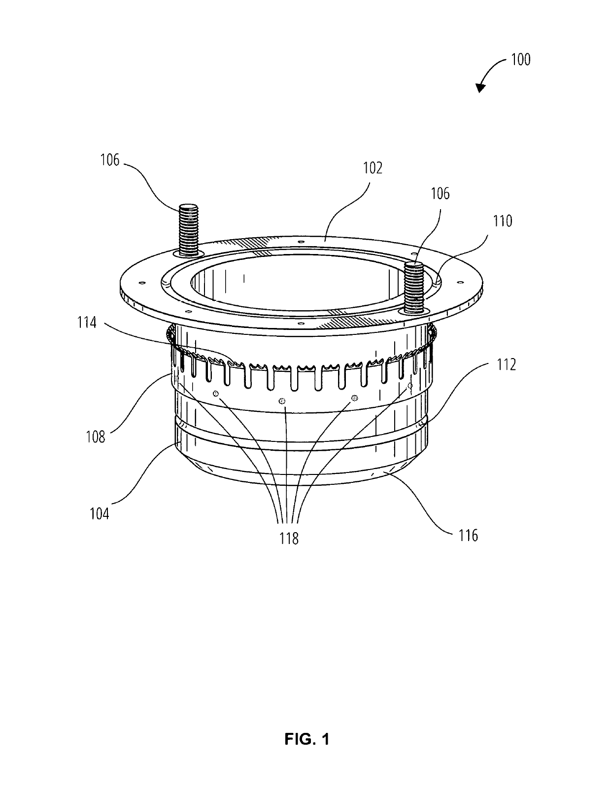
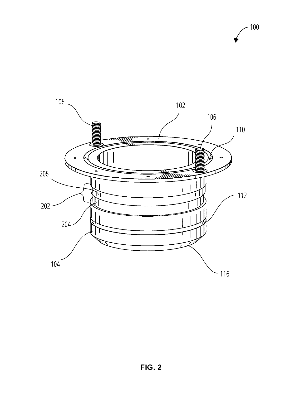
[0071]FIG. 1 shows an embodiment of a toilet flange apparatus 100 having a flange portion 102 which has a flange circumferential groove 110 which receives a first O-ring 406 (shown in FIG. 4), where the flange portion 102 and the flange circumferential groove 110 and the first O-ring 406 cooperate to form a seal with a lower portion of a toilet 904 (shown in FIG. 9). An at least one fastener 106 is used to tighten the flange portion 102 to the lower portion of the toilet 904. Fasteners 106 may include bolts, other threaded fasteners, clips, pins, and any other mechanical fastening mechanisms known in the art. In some embodiments, the fasteners 106 are formed as a portion of the flange portion 102. Although an O-ring 406 is specifically noted, one skilled in the art will appreciate that any elastomeric sealing member may be used, and that the circumferential groove 112 may have a size and dimension to accommodate such sealing members. The toilet flange apparatus 100 may be made from ...


PUM

PropertyMeasurementUnit
freedom of rotationaaaaaaaaaa
angleaaaaaaaaaa
diameteraaaaaaaaaa

Abstract

A toilet flange for facilitating installation of a toilet onto a drain pipe is provided. The toilet flange is rotationally adjustable while being irreversibly inserted into or onto the drain pipe. The toilet flange includes a flanged pipe cooperative with a circumferential gripping ring. The flanged pipe has an outer surface that includes a circumferential channel. The circumferential gripping ring cooperates with the circumferential channel so as to provide rotational adjustment while the flanged pipe is irreversibly inserted into or onto the drain pipe. The flanged pipe outer surface includes a circumferential groove for accommodating a sealing ring seated in the circumferential groove. The circumferential gripping ring includes a channel guide ring that is seated rotatably within the circumferential channel, and a plurality of gripping projections extending from the channel guide ring. The toilet flange is simpler and faster to install, providing a longer-lasting seal than a traditional toilet flange.

Description

CROSS-REFERENCE TO RELATED APPLICATIONS[0001]The present application claims priority as a Continuation in Part of U.S. patent application Ser. No. 15 / 465,390 titled, “Self-Sealing Closet Flange”, filed Mar. 21, 2017, which is a Continuation of U.S. patent application Ser. No. 13 / 930,461 titled, “Self-Sealing Closet Flange”, filed Jun. 28, 2013, and which is incorporated herein in its entirety by this reference.FIELD OF THE INVENTION[0002]This invention relates generally to plumbing fixtures, and more specifically to toilet flanges.BACKGROUND OF THE INVENTION[0003]Toilet plumbing installation and repairs are common in both new and older homes. Traditionally, a toilet, commode, or water closet is positioned on a floor surface and connected to a toilet flange, which is also known as a closet flange or a water closet flange. A toilet flange is a pipe fitting that connects the toilet to a drain pipe. Toilet flanges are usually positioned between the bottom surface of the toilet and the s...

Claims


Application Information

Patent Timeline
Patent Type & Authority Patents(United States)
IPC IPC(8): E03D11/16
CPCE03D11/16Y10T29/4943
Inventor CONNELL, DARRELL GREGORY
Owner CONNELL DARRELL GREGORY
Why Eureka
Try Eureka