
Video processor, display apparatus, and video processing method

a video processing and display device technology, applied in image enhancement, color signal processing circuits, instruments, etc., can solve the problems of low-contrast video images that are therefore undesirable to display, and achieve the effect of increasing the brightness of video images and extending the luminance range of video images

Active Publication Date: 2019-05-21
SEIKO EPSON CORP
View PDF12 Cites 0 Cited by
  • Summary
  • Abstract
  • Description
  • Claims
  • Application Information

AI Technical Summary

Benefits of technology

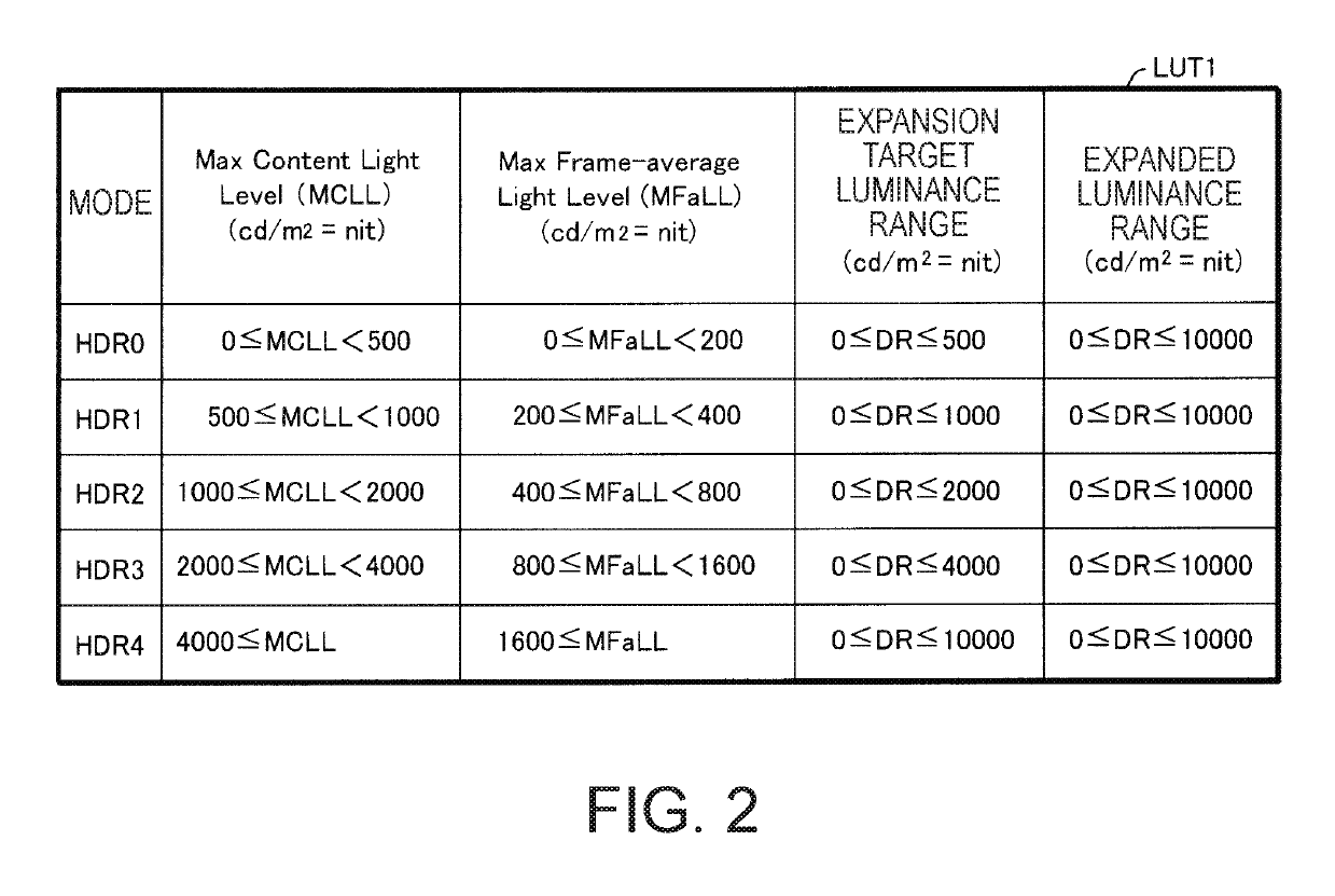
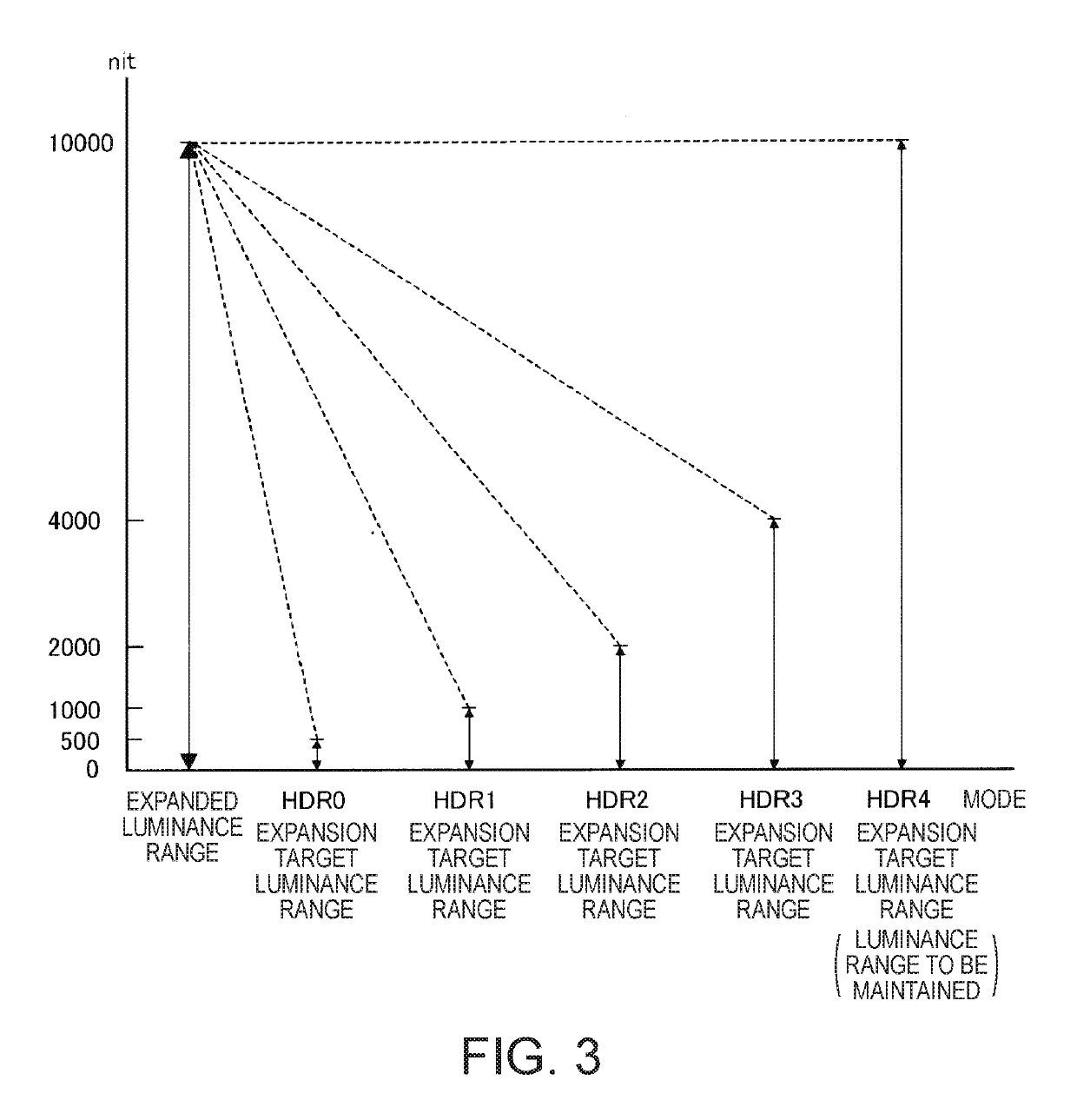
The invention provides a way to make video images brighter and have higher contrast by expanding the luminance range of video images. This is done by lowering the maximum luminance in the expansion target luminance range when luminance represented by the luminance-related information is lower. The result is that the video images will have more detail and higher quality.

Problems solved by technology

Therefore, when HDR video information representing video images having maximum luminance lower than 10000 nit is inputted to an HDR display apparatus, part of the brightness range of the HDR display apparatus, that is, the brightness range portion corresponding to the luminance range from the maximum luminance of the HDR video information to 10000 nit is not used, and dark, low-contrast video images are therefore undesirably displayed.

Method used


Image

  • Video processor, display apparatus, and video processing method
  • Video processor, display apparatus, and video processing method
  • Video processor, display apparatus, and video processing method

Examples


first embodiment

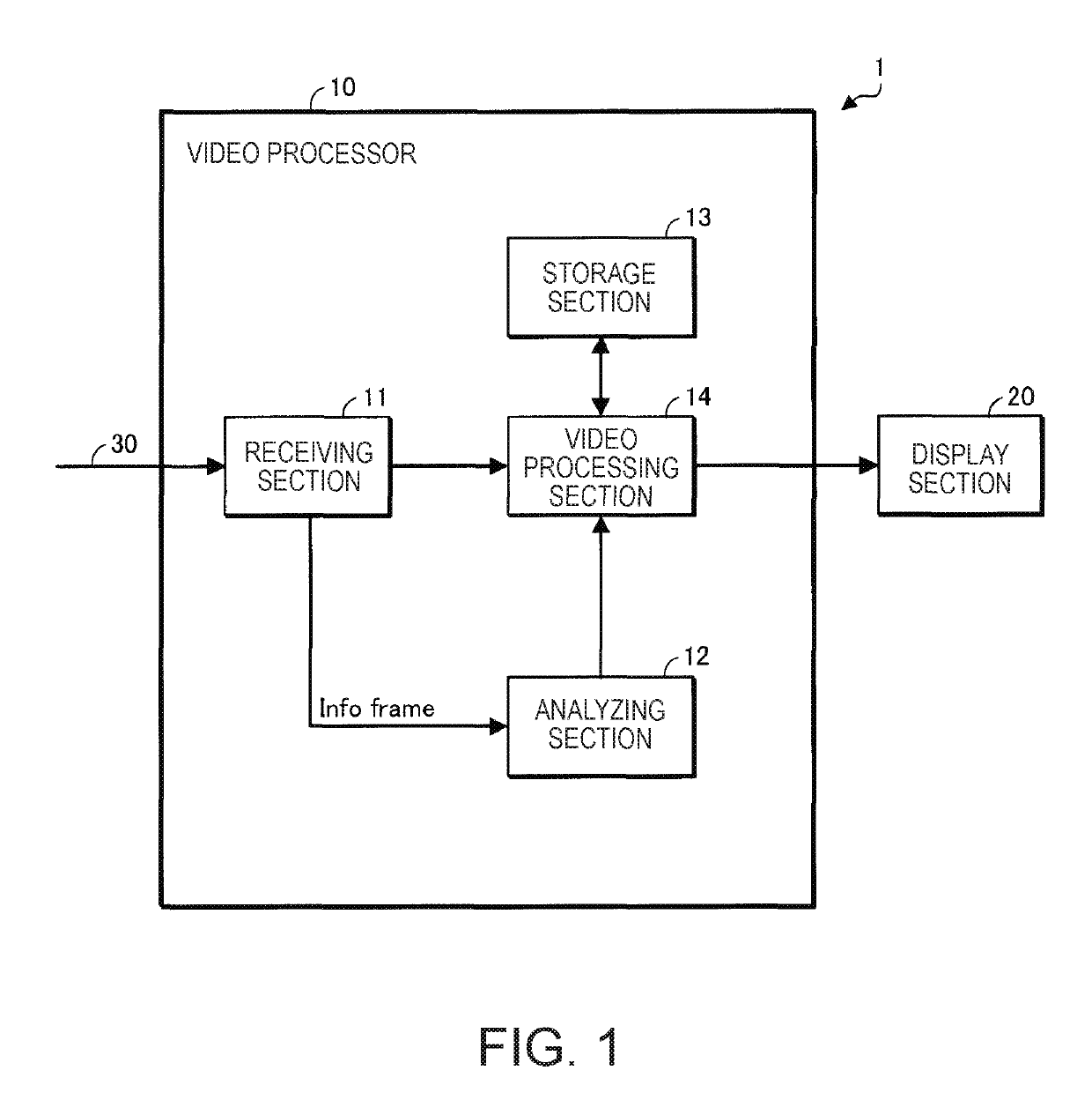
[0047]FIG. 1 shows a display apparatus 1 according to a first embodiment that adopts the invention.

[0048]The display apparatus 1 is an HDR display apparatus that supports the HDR method and is, for example, a projector. A projector is currently required to display brightest possible video images. The requirement is not limited to a projector and is common to other display apparatus.

[0049]The display apparatus 1 includes a video processor 10 and a display section 20. The brightness range of display operation performed by the display section 20 corresponds to the range of luminance that HDR video information compliant with the HDR method can take on (luminance range from 0 to 10000 nit). The video processor 10 includes a receiving section 11, an analyzing section 12, a storage section 13, and a video processing section 14.

[0050]The receiving section 11 receives a signal compliant with the HDMI standard (hereinafter referred to as “HDMI signal”) via an HDMI cable 30.

[0051]The HDMI sign...

second embodiment

[0122]In the first embodiment, the MCLL information and the MFaLL information are used as the luminance-related information.

[0123]In a second embodiment, the MaxDML information is further used as the luminance-related information. The MaxDML information is used to select a mode to be used in the case where neither the MCLL information nor the MFaLL information is written in Info Frame.

[0124]FIG. 5 shows a display apparatus 1A according to the second embodiment that adopts the invention. In FIG. 5, the same configurations as those shown in FIG. 1 have the same reference characters.

[0125]The display apparatus 1A according to the second embodiment differs from the display apparatus 1 according to the first embodiment in that a video processor 10A is provided in place of the video processor 10. The display apparatus 1A according to the second embodiment will be described below primarily on differences from the display apparatus 1 according to the first embodiment.

[0126]The video process...


PUM


Abstract

A video processor includes a receiving section that receives video information representing video images and luminance-related information on the luminance of the video images and a video processing section that determines an expansion target luminance range of the video images based on the luminance-related information and expands the expansion target luminance range in such a way that the maximum luminance in the expansion target luminance range increases.

Description

CROSS-REFERENCE[0001]The entire disclosure of Japanese Patent Application No. 2016-124817, filed Jun. 23, 2016 is expressly incorporated by reference herein.BACKGROUND[0002]1. Technical Field[0003]The present invention relates to a video processor, a display apparatus, and a video processing method.[0004]2. Related Art[0005]As a new method relating to video images, an HDR (high dynamic range) method has been known (see JP-A-2016-34125). In the HDR method, a luminance of 10000 nit is specified as the maximum luminance. It is noted that 1 nit is 1 cd / m2.[0006]In an HDR display apparatus that supports the HDR method, the display brightness range corresponds to the range of luminance that HDR video information compliant with the HDR method can take on (specifically, luminance range from 0 to 10000 nit). For example, an HDR display apparatus, when displaying video images represented by HDR video information, displays a video image portion having a luminance of 10000 nit with the brightes...

Claims


Application Information

Patent Timeline
Patent Type & Authority Patents(United States)
IPC IPC(8): G09G3/14G06F3/14H04N5/232H04N5/243H04N9/73H04N9/64H04N5/57H04N5/235G06T5/00G06T11/00G09G3/20G09G5/02G09G5/10H04N23/76
CPCH04N5/2355G06F3/14G09G5/10H04N5/243H04N5/57H04N5/23232G09G2370/04G09G2320/0271G09G5/00G09G2320/0285G09G2320/0613G09G2320/0626G09G2370/042G09G2370/12H04N23/741H04N23/76H04N23/951
Inventor NAGANO, MIKIHAYASHI, YOSHIHITOTSUBOI, SACHIOKOBAYASHI, ISAO
Owner SEIKO EPSON CORP
Learn More