
Lighting device

a technology of light-emitting devices and light-emitting devices, which is applied in the direction of semiconductor devices for light sources, point-like light sources, lighting and heating apparatus, etc., can solve the problems of increasing installation cost and power consumption, and increasing the number of indoor lighting devices. , to achieve the effect of enhancing luminance, reducing light loss, and expanding the luminous range of light-emitting devices

Inactive Publication Date: 2013-03-26
KWO GER METAL TECH
View PDF2 Cites 0 Cited by
  • Summary
  • Abstract
  • Description
  • Claims
  • Application Information

AI Technical Summary

Benefits of technology

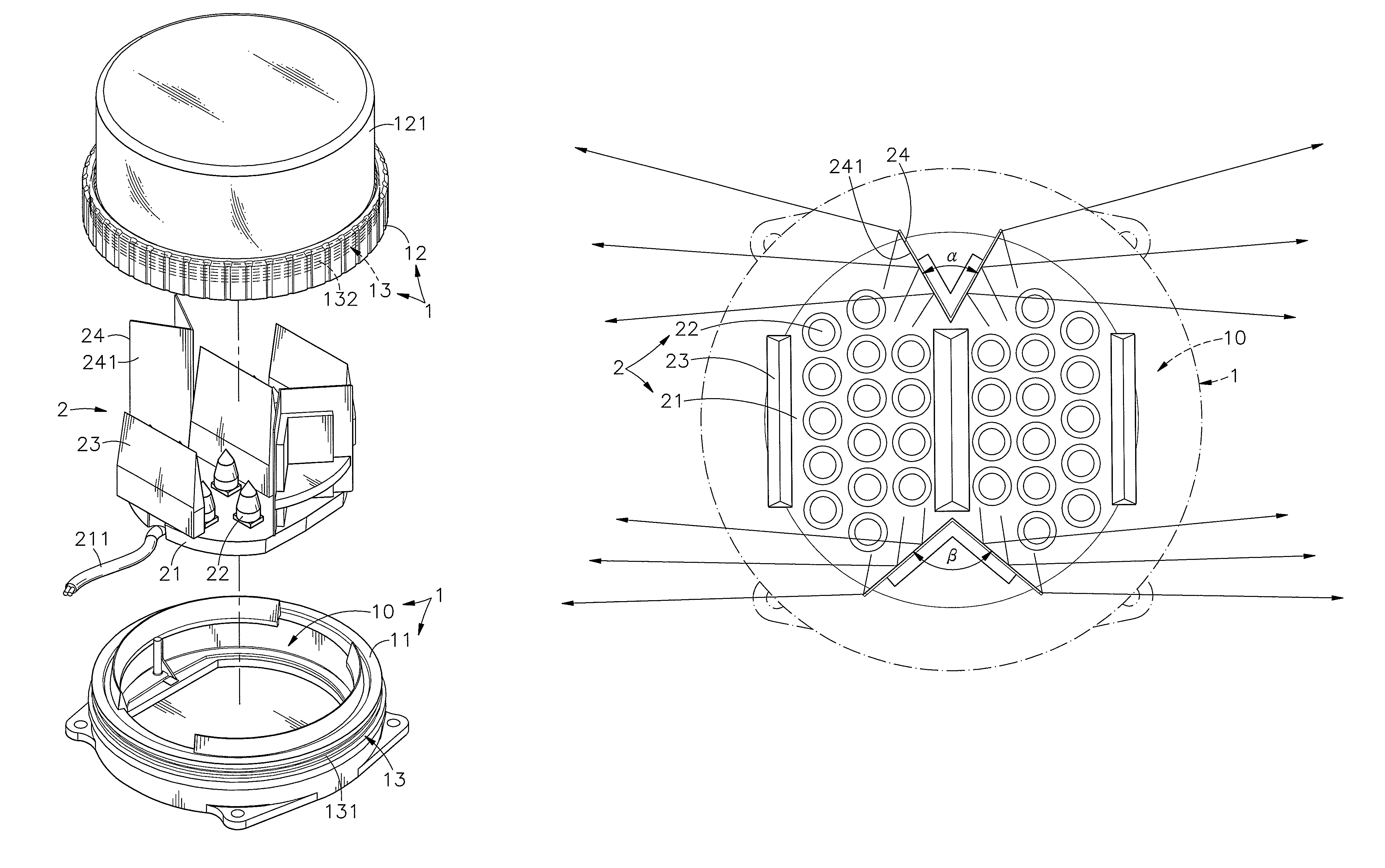
The present invention is a lighting device that increases the luminous range, enhances luminance, and reduces light loss. It includes a housing and a light-emitting module mounted inside the housing. The light-emitting module has a circuit board carrying multiple light-emitting devices, refracting prisms, and double-beveled reflectors. The refracting prisms refract part of the light emitted in a horizontal direction toward two opposing sides through the top cover shell of the housing. The double-beveled reflectors reflect the other part of the light emitted in the same opposing direction. This lighting device extends its luminous range, enhances luminance, and reduces light loss.

Problems solved by technology

However, increasing the number of lamps relatively increases the installation cost and power consumption.
However, conventional lighting devices, either for indoor application or outdoor application, still have numerous drawbacks as follows:
1. In consideration of the limited luminous range of conventional street lights, the installation interval must be shortened to maintain the desired luminance; however increasing the number of street lights relatively increases the consumption of power supply.
2. Due to the drawback of limited luminous range of conventional indoor lighting devices, the number of lighting devices in an indoor space must be relatively increased to maintain the desired luminance; however increasing the number of indoor lighting devices relatively increases the installation cost and the consumption of power supply.
3. Due to the limitation that the luminous area of conventional indoor lighting devices and outdoor lighting devices is a circular area, the brightness in the circular luminous area is not uniform, lowering the effect of illumination.

Method used


Image

  • Lighting device
  • Lighting device
  • Lighting device

Examples


Embodiment Construction

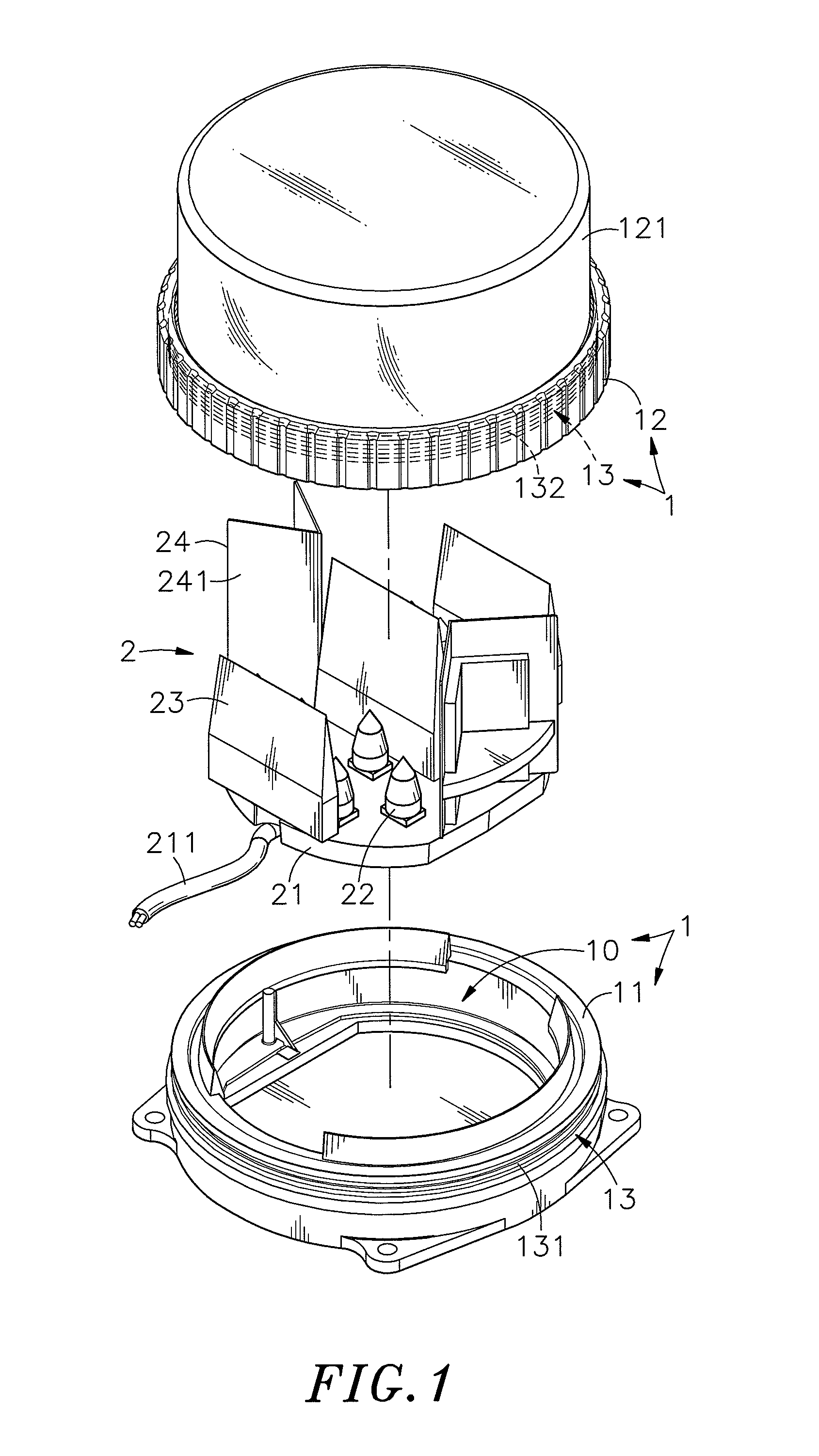
[0021]Referring to FIGS. 1˜4, a lighting device in accordance with the present invention is shown comprising a housing 1 and a light-emitting module 2.

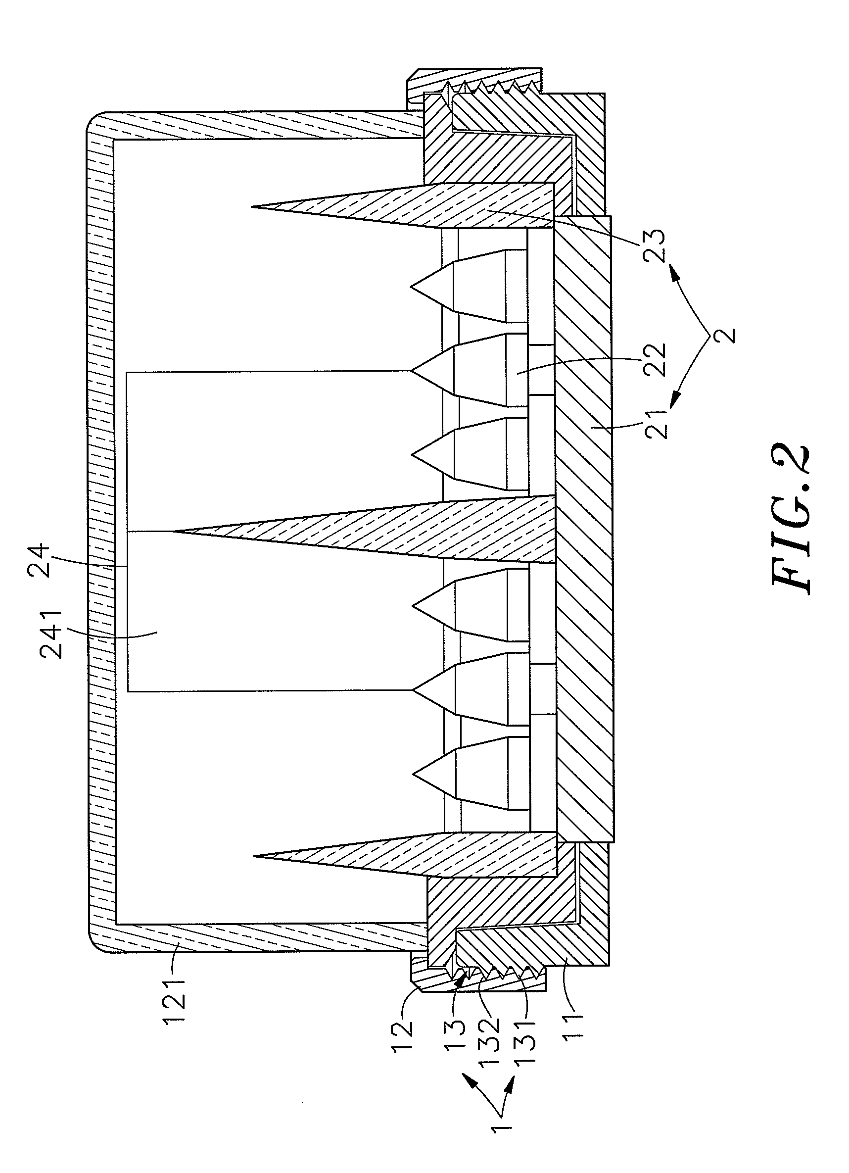
[0022]The housing 1 is formed of a bottom shell 11 and a top cover shell 12. The bottom shell 11 and the top cover shell 12 define therein an accommodation chamber 10. The top cover shell 12 has a light transmissive peripheral wall 121 extending around the accommodation chamber 10. By means of a mounting structure 13, the bottom shell 11 and a top cover shell 12 are fastened together.

[0023]The light-emitting module 2 comprises a circuit board 21 carrying a circuit layout, a power source 211 electrically connected to the circuit board 21, a plurality of light-emitting devices 22 installed in the circuit board 21, a plurality of refracting members, for example, refracting prisms 23 mounted on the circuit board 21 for refracting the light emitted by the light-emitting devices 22 and adapted to refract the light emitted by the light-emitt...


PUM


Abstract

A lighting device includes a housing, and a light-emitting module mounted in an accommodation chamber inside the housing and carrying a set of light-emitting devices on a circuit board thereof for emitting light, a plurality of refracting prisms for refracting a part of the light emitted by the light-emitting devices horizontally toward two opposing sides through the light transmissive peripheral wall of the top cover shell of the housing and two opposing double-beveled reflectors for reflecting the other part of the light emitted by the light-emitting devices toward the outside through the light transmissive peripheral wall of the top cover shell of the housing in the same opposing directions. Thus, the invention extends the luminous range of the light-emitting devices, enhances the luminance and reduces light loss.

Description

[0001]This application claims the priority benefit of Taiwan patent application number 098218162, filed on Oct. 1, 2009.BACKGROUND OF THE INVENTION[0002]1. Field of the Invention[0003]The present invention relates to lighting technology and more particularly, to a lighting device, which extends the luminous range of the light-emitting devices thereof, enhances the luminance and reduce light loss.[0004]2. Description of the Related Art[0005]The invention of lamp changes the living style of human beings, enabling people to work at night. Nowadays, many different types of lamps have been created for different applications, for example, fluorescent lamps, desk lamps, wall lamps and ceiling lamps for indoor lighting, street lights for outdoor lighting and signal lights for traffic guide and warning applications. Regular outdoor lights commonly emit light through 360° angle. During operation, the light intensity reduces gradually in all directions from the center area toward the distal ar...

Claims


Application Information

Patent Timeline
Patent Type & Authority Patents(United States)
IPC IPC(8): F21V17/00
CPCF21V5/02F21V7/10F21Y2101/02F21Y2115/10
Inventor CHENG, CHIN-YUANCHEN, HONG-LONG
Owner KWO GER METAL TECH
Learn More