Increased color depth, dynamic range and temporal response on electronic displays

a technology of dynamic range and temporal response, applied in the field of display of video image information, can solve the problems of high power consumption, ineffective techniques, and high price of bright backlight, and achieve the effect of increasing dynamic luminance range and color depth

Inactive Publication Date: 2009-06-09
SAMSUNG ELECTRONICS CO LTD
View PDF13 Cites 0 Cited by
  • Summary
  • Abstract
  • Description
  • Claims
  • Application Information

AI Technical Summary

Benefits of technology

[0006]In one embodiment, the present invention provides a display method and system maps each source image pixel from a source device into several display pixels on a display screen, where the characteristics of the display pixels are selectively controlled to provide desired visual effects such as multiple luminance levels, increased color depth, increased dynamic luminance range, manipulation of temporal characteristics of the display, etc.
[0007]According to an embodiment of the present invention, each source image pixel (from a source device) is mapped to several display pixels on a screen, wherein the display pixels are selectively controlled to provide desired visual effects such as additional color depth and dynamic range, improved perceived temporal response characteristics of the display, etc.
[0009]In another embodiment, the n display pixels representing a single source image pixel are adjusted by following a color mapping scheme to provide additional color depth. For example, in the set of n display pixels, pixel #1 is driven with additional grayscale values, pixel #2 is driven with x % of the source image pixel grayscale values, pixel #3 is driven with y % of the source image pixel grayscale values, etc. When averaged and integrated by the user's visual system, the n pixels appear to provide additional color depth.
[0010]In another embodiment, the dynamic luminance range of the displayed image may be enhanced by only using one or more of the n display pixels associated with a single source image pixel when the source image pixel has a high luminance value (e.g., it is white). Selective increase of the dynamic range over one or more regions of the source image and / or particular grayscale range(s) can also be utilized.

Problems solved by technology

However, a bright backlight is expensive and consumes high power.
However, such techniques are often ineffective and further require additional hardware to achieve any results.
Further, conventional displays are limited to 8 bits of color depth, even when using spatial or temporal dithering to enhance color depth.
Displays that can display more than 8 bits of color depth are problematic because the levels above 8 bits are very close together in voltage terms whereby any noise causes a cross-over leading to artifacts.
In addition, mainstream digital interfaces (e.g., DVI, HDMI, etc.) cannot conveniently utilize more than 8 bits for color depth for display.
Another shortcoming of conventional displays systems such as LCD and Plasma (relative to CRTs) is that the maximum luminance in such displays cannot be selectively enhanced depending on the source image, whereby image contrast suffers.
LCD displays do not provide such capability and resort to a very bright backlight for contrast.
However, a bright backlight is expensive and consumes high power.
Plasma displays drive the display harder for higher contrast ratio, resulting in higher power consumption, cost and shorter display life.
Yet another problem with LCDs is their relatively slow pixel state transition (slow temporal response characteristics) relative to that possible in CRTs.
The slowness causes undesirable artifacts such as blurring and ghosting for fast moving objects in images (e.g., sports, games, etc.).
However, this causes considerable flickering of the displayed images unless LCD display is operated at a higher frame rate than normal which requires non-standard design at a higher cost.

Method used


Image

  • Increased color depth, dynamic range and temporal response on electronic displays
  • Increased color depth, dynamic range and temporal response on electronic displays
  • Increased color depth, dynamic range and temporal response on electronic displays

Examples


Embodiment Construction

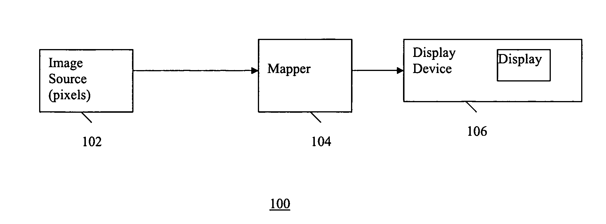
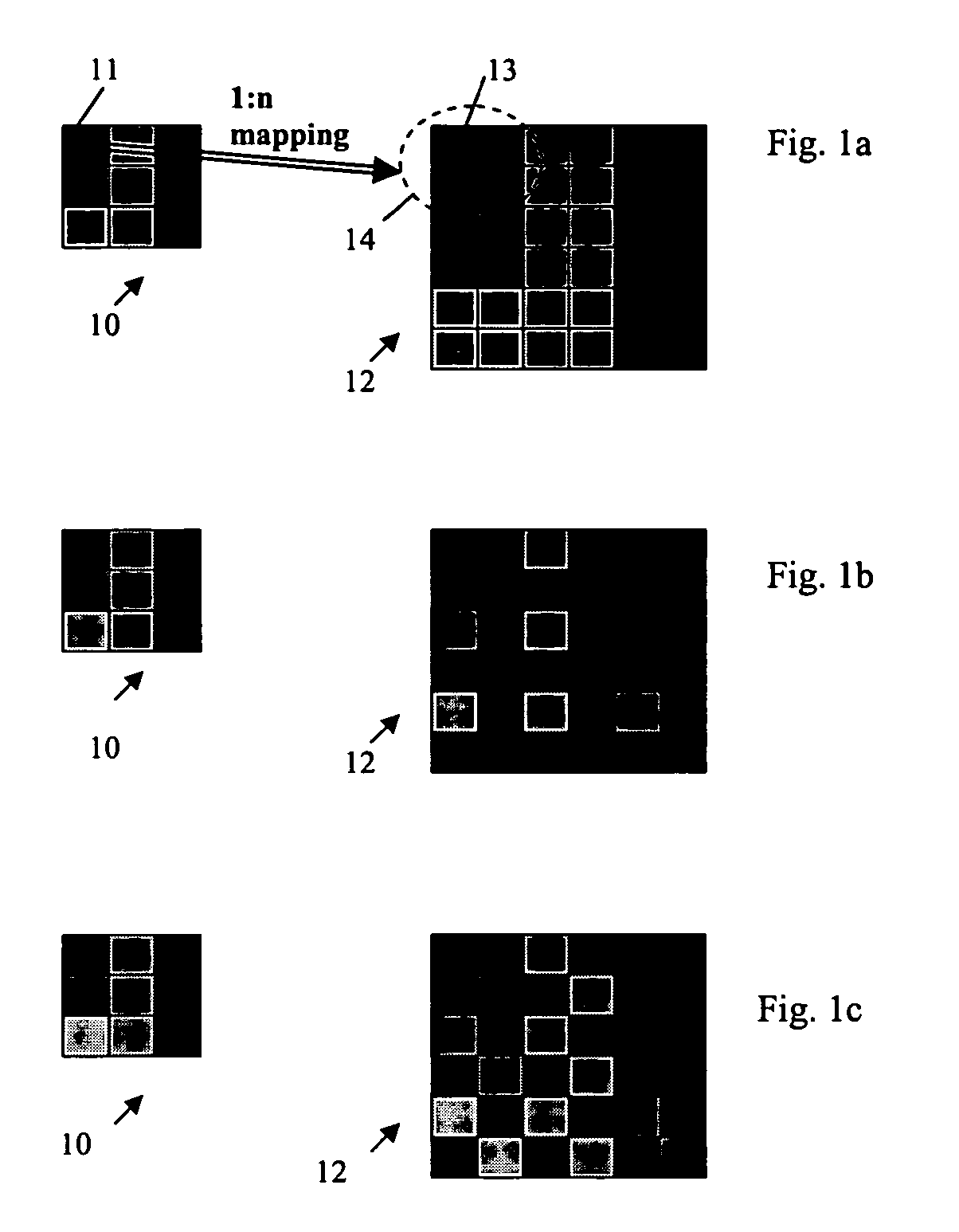
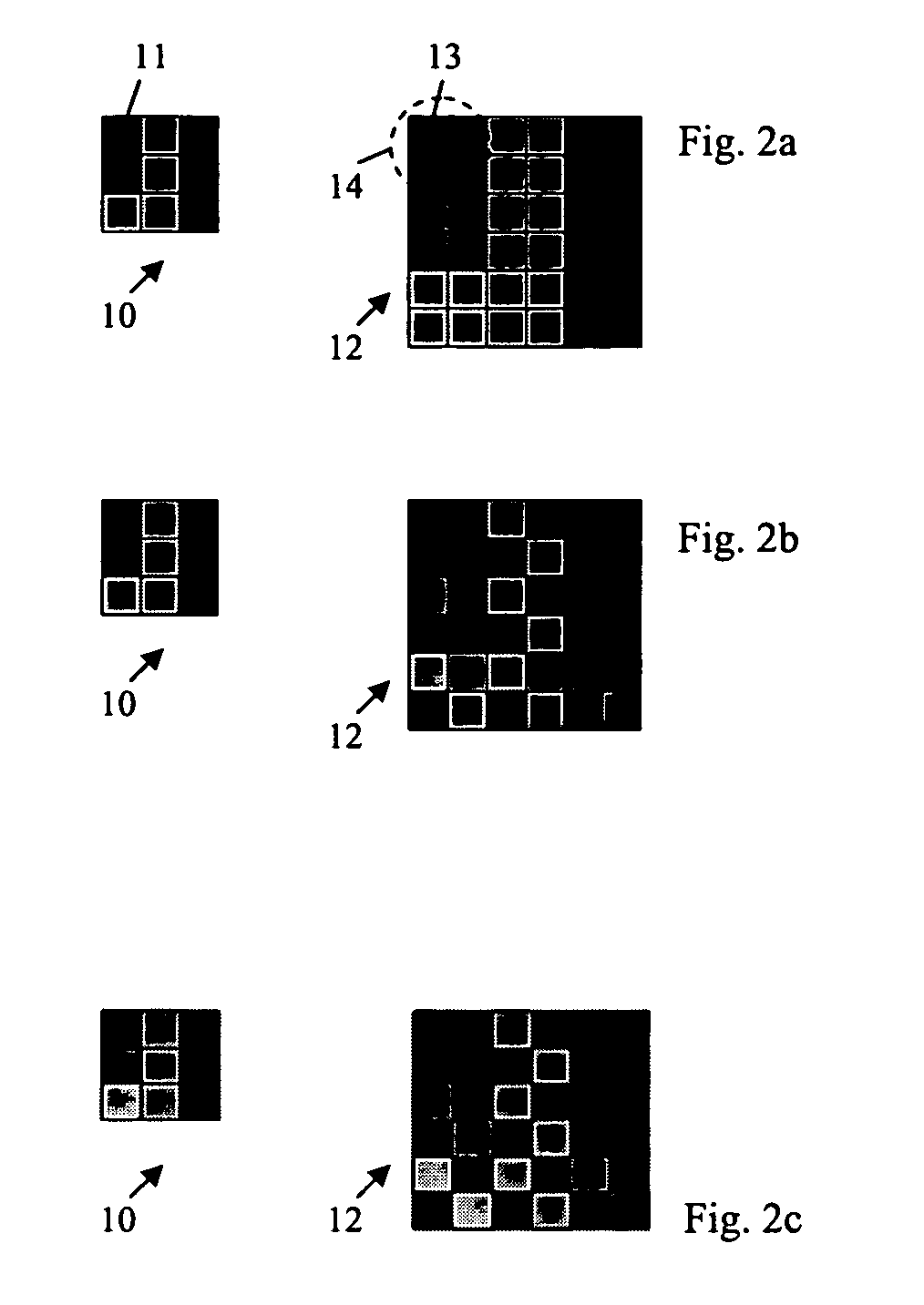
[0030]A method of selectively mapping each pixel from a source image into n display pixels for display on a display screen (i.e., 1:n mapping wherein n is a positive integer), may be based on the pixel resolution of the input image and the native resolution of the display device, wherein the mapping provides a display image pixel format that is essentially optimized for display on the display device.

[0031]When a source image pixel (from a source device) is represented on a display by several (e.g., n) display pixels, according to an embodiment of the present invention, the characteristics of the display pixels are selectively controlled to provide desired visual effects such as: multiple luminance levels, increased color depth, increased dynamic luminance range, manipulation of temporal characteristics of the display, etc. Example embodiments of mapping of a source image pixel into several display pixels while selectively controlling characteristics of the display pixels, according ...


PUM


Abstract

A display method and system maps each source image pixel from a source device into several display pixels on a display screen, where the characteristics of the display pixels are selectively controlled to provide desired visual effects such as multiple luminance levels, increased color depth, increased dynamic luminance range and manipulation of temporal characteristics of the display.

Description

FIELD OF THE INVENTION[0001]The present invention relates in general to displaying video image information, and in particular to enhancing display of video image information.BACKGROUND OF THE INVENTION[0002]Many display systems are being used to display different types of source images such as those generated by office software applications, video games, movies, etc. For these different types of source images, there are different luminance levels for display. For example, office applications (e.g., word processor) and video games are two difference extremes. In office applications, typically a very bright display screen relative to the background is not desired, whereas in entertainment applications such as video games user prefer visual effects of a bright display screen (higher luminance level) relative to the background. Conventionally, for displays such as LCD and Plasma, perception of higher level of luminance is achieved by increasing the power output of the display backlight....

Claims


Application Information

Patent Timeline
Patent Type & Authority Patents(United States)
IPC IPC(8): G09G5/00G09G3/28G09G3/30G09G5/10H04N5/57H04N5/74
CPCG09G3/20G09G3/2051G09G2320/0626G09G2320/10G09G2360/144H04N9/64
Inventor MILLER, IAN
Owner SAMSUNG ELECTRONICS CO LTD
Why Eureka
Try Eureka