Single-groove and short-tail pulling rivet and erection method thereof

a single-groove, short-tail technology, applied in the direction of threaded fasteners, screwdrivers, mechanical equipment, etc., can solve the problems poor tightening of claws, and large impact force and noise, etc., to solve the problem of high positioning requirements, easy jamming of the broached groove, and insufficient tightening

Active Publication Date: 2019-06-04
MEISHAN CRRC FASTENING SYST CO LTD
View PDF3 Cites 0 Cited by
  • Summary
  • Abstract
  • Description
  • Claims
  • Application Information

AI Technical Summary

Benefits of technology

[0006]The invention provides a single-groove and short-tail pulling rivet and an erection method thereof, aiming at solving high positioning requirements, easily jammed broached groove, stress concentration, poor tightness of the claw and insufficient tightening force of the locking groove section during riveting of existing short-tail pulling rivets, so as to meet performance and reliability requirements of the fastening system of the components of rolling stock.
[0017]1) A rivet with single-groove short tail can be manufactured more easily and reduce manufacturing cost effectively compared with a rivet with a multi-groove short tail. The requirements for using a rivet with a single-groove short tail are less rigorous than a rivet with a multi-groove short tail, and a rivet with a single-groove short tail can be conveniently arranged.
[0019]3) The tooth profile of the locking groove section 1.3 of the rivet is a smooth curve combining an arc with a straight line; despite comparable tightening force compared with the locking groove section of existing short-tail pulling rivets, such tooth profile can be easily defected due to small processing difficulty and more suitable for rotation and coordination of the snap tooth of the collar, which greatly reduces the difficulty of manufacturing a snap tooth of a collar. In general, manufacturing cost and detection cost of products are greatly reduced without compromising use performance.
[0020]4) The design parameter of the collar is M / N=0.15-0.4, and the flange plate has strong anti-pressure ability. Thus, deformation of the collar can be reduced and tightening force of the locking groove section increases. When riveting a non-circular hole by existing riveting technology (non-circular hole formed by tolerance or mounting hole, i.e. the condition that a riveting hole can allow a rivet to pass but cannot meet the use requirements), the collar is always deformed during erection and loses tightening force on the locking groove section. However, the invention provides the above collar design to avoid such condition.
[0022]6) The more simple and effective end face (claw positioning face) positioning method is used during erection.

Problems solved by technology

The disadvantages are as follows: the riveting process requires snapping the separating groove and abandoning the pull rod, there are large impact force and noise, poor environmental protection and material waste during riveting, and the hydraulic riveting machine requires large riveting pressure and large diameter of an oil cylinder and heavy weight.
② tightness between a short tail with existing annular groove shape and a claw of the riveting machine is limited, which fails to meet the requirements of the rolling stock provided with a fastening system requiring higher performance and reliability.
③ short-tail pulling rivets with annular groove section cannot be erected conveniently.
Under severe operation conditions, a broached groove of a multi-groove short tail rivet may be easily blocked, possibly causing riveting defeat and damaging the riveting machine.
Thus, existing single-groove short tail may subject to tooth shape damage due to axial force when the claw of a riveting machine is not engaged with the broached groove well during actual riveting.
Such tooth profile cannot be easily processed and detected, and its mould cannot be easily manufactured at low cost.

Method used


Image

  • Single-groove and short-tail pulling rivet and erection method thereof
  • Single-groove and short-tail pulling rivet and erection method thereof
  • Single-groove and short-tail pulling rivet and erection method thereof

Examples


Embodiment Construction

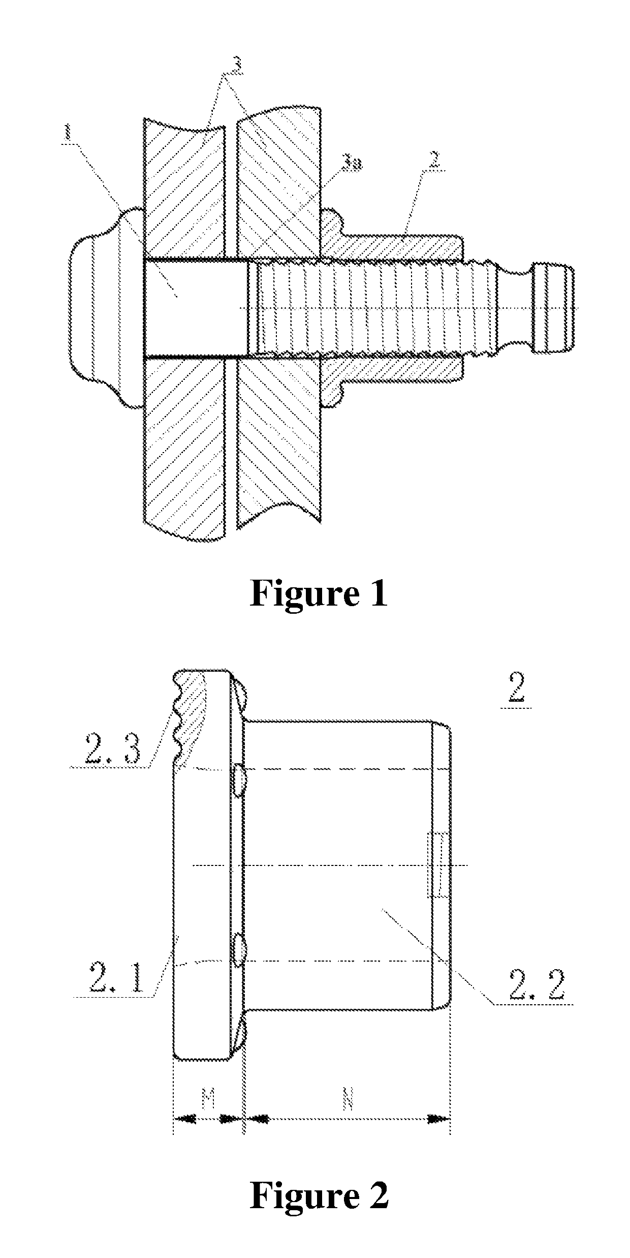
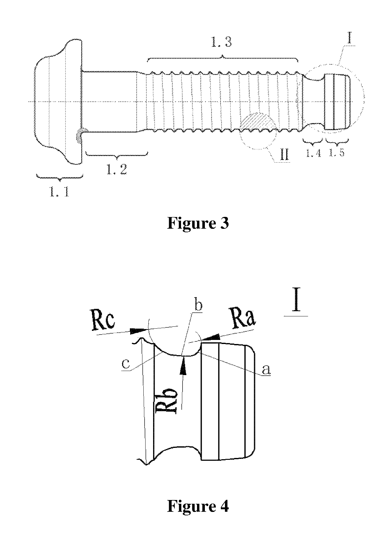
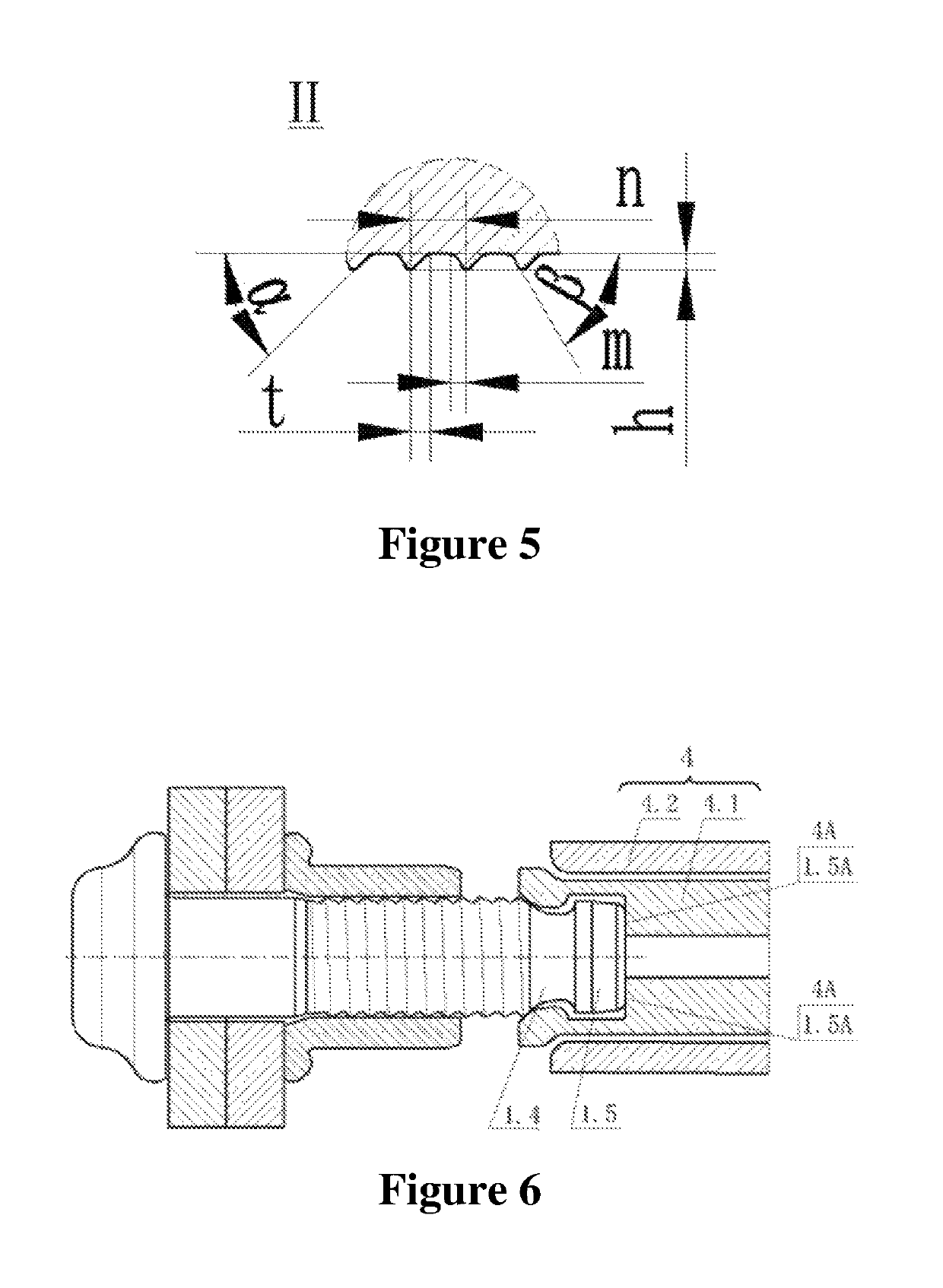
[0036]See FIG. 1, the single-groove and short-tail pulling rivet in the example consists of a rivet 1 and a collar 2. See FIG. 3, the rivet 1 comprises a rivet head 1.1, a polished rod 1.2, a locking groove section 1.3 and a short tail connected in order from front to back. See FIG. 2, the collar 2 comprises a flange 2.1 and a sleeve 2.2 from front to back. See FIG. 1, the collar 2 is arranged on the locking groove section 1.3. New design of the invention is as follows:[0037]1) See FIG. 3, the short tail is a single-groove short tail consisting of a broached groove 1.4 with a continuous and smooth curve, and a short tail tooth 1.5; i.e. the single-groove short tail consists of a broached groove 1.4 with a continuous and smooth curve, and a short tail tooth 1.5.[0038]2) See FIG. 4, the broached groove 1.4 with a continuous and smooth curve is designed such that a smooth and continuous cambered surface is formed by three sections of arcs c, b and a with different radii in order from f...


PUM

PropertyMeasurementUnit
radiiaaaaaaaaaa
radiusaaaaaaaaaa
Raaaaaaaaaaa

Abstract

Provided is a single-groove and short-tail pulling rivet and an erection method thereof, and the pulling rivet comprises a single groove and a short tail having a broached groove with a continuous and smooth cambered surface, and is characterized by easy manufacturing, low cost and convenient erection. The broached groove is an arc surface with three sections of different radiuses, which solves stress concentration and sticking of a single-groove and short-tail rivet during riveting, and allows a claw of a riveting machine to be engaged to the best position automatically. The tooth profile of a locking groove section of the rivet is a curve combining an arc and a straight line, which greatly improves fastening force. In a word, the invention solves insufficient clamping degree of the short tail, seizing during riveting, blocking of the broached groove, failed riveting, shortage and loss of tightness of existing short-tail pulling rivets, and meets the performance and reliability requirements of the fastening systems for rolling stocks.

Description

(1) FIELD OF THE INVENTION[0001]The invention relates to a single-groove and short-tail pulling rivet and an erection method thereof, in particular to a cold-drawn riveting technology, mainly used for connecting components of rolling stock. The invention belongs to riveting (B21J) and fastener (F16B) in the metal mechanical processing field.(2) DESCRIPTION OF THE RELATED ART[0002]The similar contents between cold-drawn rivets used for connecting components of rolling stock and the connection method thereof disclosed in the prior art and the invention are as follows: 1) See Pulling Rivets (ZL200520035325.X) disclosed in Chinese Patent for ordinary pulling rivets. The disadvantages are as follows: the riveting process requires snapping the separating groove and abandoning the pull rod, there are large impact force and noise, poor environmental protection and material waste during riveting, and the hydraulic riveting machine requires large riveting pressure and large diameter of an oil...

Claims


Application Information

Patent Timeline
Patent Type & Authority Patents(United States)
IPC IPC(8): B21J15/02B21J15/04F16B19/05F16B19/10
CPCF16B19/10B21J15/022F16B19/05B21J15/045F16B2019/1009B21J15/14F16B19/08
Inventor HE, XULIU, YUFU, KAIZHANG, XIONGJIA, YUNLONGDAI, GUANGCHENGLI, XINRONGWANG, XIAWAN, YONG
Owner MEISHAN CRRC FASTENING SYST CO LTD
Why Eureka
Try Eureka