
Card edge connector

a card edge and connector technology, applied in the direction of coupling contact members, coupling device connections, securing/insulating coupling contact members, etc., can solve the problems of difficult design of terminals smaller and more compact, avoid permanent deformation and prevent excessive deflection of flat plate terminals. , the effect of easy overflow

Active Publication Date: 2019-06-04
MOLEX INC
View PDF6 Cites 7 Cited by
  • Summary
  • Abstract
  • Description
  • Claims
  • Application Information

AI Technical Summary

Benefits of technology

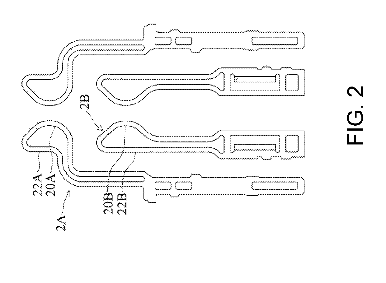
The present invention introduces a flat plate-shaped terminal with a two-arm configuration and a closed loop, which can successfully control deflection behavior and prevent permanent deformation of the terminal. By having different profiles and widths of the inner and outer arms, the two-arm configuration can reduce stress concentration on certain sections of the terminal, leading to a higher overall stress tolerance. Additionally, the spacing between certain sections of the inner and outer arms can further improve the terminal's performance. In contrast, existing terminals with similar widths for the two planar beam sections are more prone to permanent deformation due to exceeded stress.

Problems solved by technology

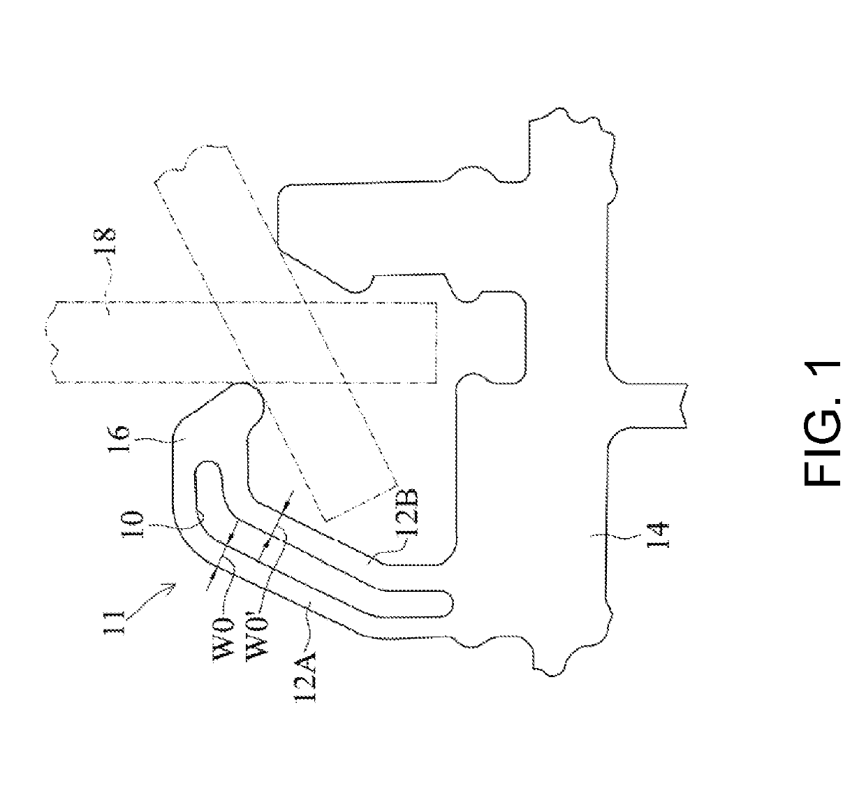
The tensile forces and compressive forces to which the planar beam sections 12A and 12B are subjected are different, of course, one way is to increase the widths and thicknesses of the planar beam section 12A and 12B at the same time to overcome the maximum plastic deformation of the planar beam section 12A and 12B, but if it does so, the connector and terminal will be difficult to design smaller and more compact.

Method used


Image

  • Card edge connector
  • Card edge connector
  • Card edge connector

Examples


Embodiment Construction

[0038]The following disclosed content provides various embodiments or exemplifications used to implement various features of the present disclosure. Specific examples of elements and arrangements are described as follows, so as to simplify the disclosed content of the present disclosure. Certainly, these are merely examples, and are not used to limit the present disclosure. For example, in the following description, that a first feature is formed on or above a second feature may comprise an embodiment that the first feature and the second are formed to directly contact with each other, may also comprise an embodiment that other feature is formed between the first feature and the second feature, therefore the first feature and the second feature do not directly contact with each other. Moreover, the present disclosure may allow a symbol and / or a character of an element to be repeated in different examples. The repetition is used for simplification and clearness, but is not used to do...


PUM


Abstract

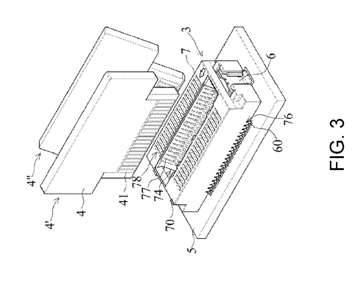
A card edge connector comprising a plurality of flat plate-shaped terminals, each of which comprises an elastic arm portion. The elastic arm sequentially comprises a lower reverse bent section, an outward inclined arm section, an upper reverse bent section and an inward inclined arm section. The elastic arm is a two-arm configuration with a closed loop, the two-arm configuration has an inner arm and an outer arm. The inner arm and the outer arm each have the corresponding lower reverse bent section, the corresponding outward inclined arm section, the corresponding upper reverse bent section and the corresponding inward inclined arm section. The width of the upper reverse bent section of the inner arm is the largest among the sections of the inner arm and the sections of the outer arm. Because the upper reverse bent section has the largest width, it can prevent excessive deflection of the flat plate-shaped terminal.

Description

RELATED APPLICATIONS[0001]This application claims priority to Chinese Application No. 201710574511.8, filed Jul. 14, 2017, which is incorporated herein by reference in its entirety.TECHNICAL FIELD[0002]The present disclosure relates to a card edge connector, especially to a card edge connector used for assembling a card edge module.BACKGROUND ART[0003]FIG. 1 is a structural schematic view of a terminal 11 of an existing card edge connector which is disclosed in U.S. Pat. No. 4,832,617 (corresponding to Taiwanese patent application No. TW77211193). Referring to FIG. 1, the terminal 11 is a terminal in form of a planar conductive member, which has a central cutout 10 to form planar beam sections 12A and 12B generally parallel to each other and spaced apart from each other, and ends of the planar beam sections 12A and 12B away from the base 14 are connect together at a part 16. The planar beam sections 12A and 12B both have uniform and identical widths (i.e., a width W0 of the planar b...

Claims


Application Information

Patent Timeline
Patent Type & Authority Patents(United States)
IPC IPC(8): H01R12/73H01R13/11H01R12/57
CPCH01R12/737H01R13/112H01R12/57H01R12/72H01R13/24H01R13/40H01R12/721H01R12/73H01R13/2407H01R13/2442H01R13/426
Inventor TAN, CHIN GUAN
Owner MOLEX INC
Learn More