Stabilizer link

a stabilizer and link technology, applied in the direction of interconnection systems, vehicle components, pivoted suspension arms, etc., can solve the problems of reducing the total lateral traction limit of a vehicle, affecting the stability of the suspension, and the driver will experience a loss of control, so as to reduce the flexing and deflection of the suspension components, improve the bending stiffness, and reduce the effect of mass

Inactive Publication Date: 2016-09-29
TOYOTA MOTOR ENGINEERING & MANUFACTURING NORTH AMERICA
View PDF5 Cites 5 Cited by
  • Summary
  • Abstract
  • Description
  • Claims
  • Application Information

AI Technical Summary

Benefits of technology

[0014]The present disclosure is directed to a vehicle suspension stabilizer bar endlink optimized for bending stiffness through the use of contoured cross sections. A contoured endlink shape provides for improved bending stiffness while minimizing mass compared with an endlink that is not contoured. The result of using stabilizer bars with endlinks of contoured shape and varying cross sections, according to the present disclosure, is the ability to more precisely design and tune vehicle handling because there is less uncontrolled flexing and deflection of suspension components. Vehicle testing has confirmed that use of contoured endlink assemblies result in greater steering efficiency and reduced response time. For a given steering torque input, a greater yaw angle output is achieved.

Problems solved by technology

Furthermore, the relative stiffness between the front and rear suspension will strongly influence the amount of weight that is transferred from side to side as well as between the front and rear tires.
If the centrifugal force of the center of gravity exceeds the available lateral force in the tires the driver will experience a loss of control as some or all of the tires begin to slide laterally.
Further, because the vehicle center of gravity is above the ground plane and usually not located at the suspension roll center, the force at the center of gravity creates a moment or torque about the roll center of the suspension at each end of the vehicle.
In general vehicle body roll has the undesirable effect of reducing a vehicle's maximum cornering ability by increasing the amount of vertical load transferred from the inside tires to the outside tires, reducing a vehicle's total lateral traction limit.
For a given set of conditions, a loss of control generally occurs sooner in a vehicle that exhibits a high degree of body roll.
This is undesirable for two reasons.
Secondly, the increase in vertical loads on the outside tires may exceed their operating capacity, also reducing the amount of lateral traction available from the outside tires.

Method used


Image

  • Stabilizer link
  • Stabilizer link
  • Stabilizer link

Examples


Embodiment Construction

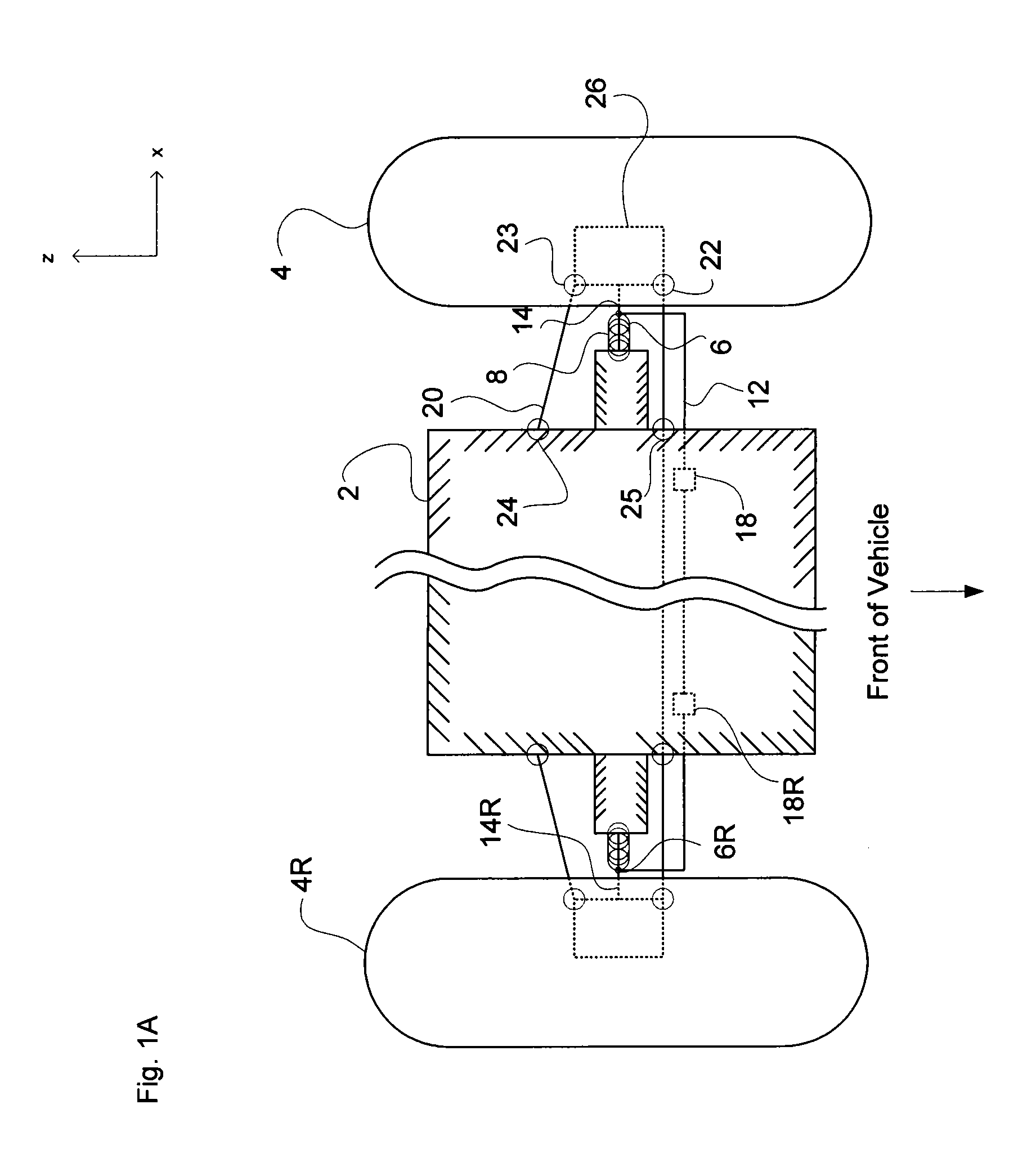
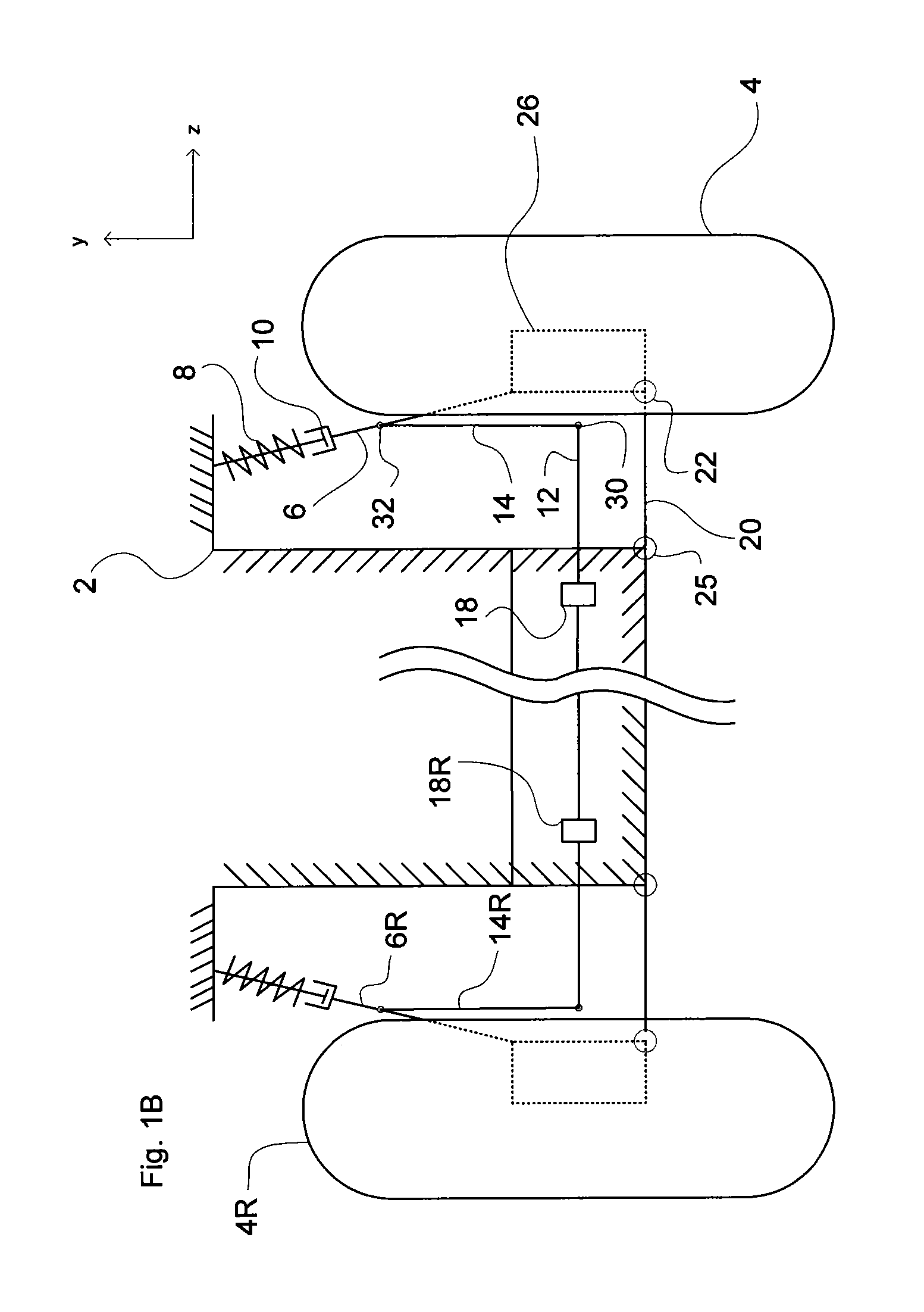
[0021]In the drawings, like reference numerals designate identical or corresponding parts throughout the several views. Further, as used herein, the words “a”, “an” and the like generally carry a meaning of “one or more”, unless stated otherwise. Further, numerals represent components and aspects of the right side of a vehicle with the exception of 2 and 12, of which there is only one of each, and both are also symmetrical about the vehicle. Lastly, references to components on the right side of the vehicle are designated by the letter “R” after the numeral. The drawings are generally drawn to scale unless specified otherwise or illustrating schematic structures or flowcharts.

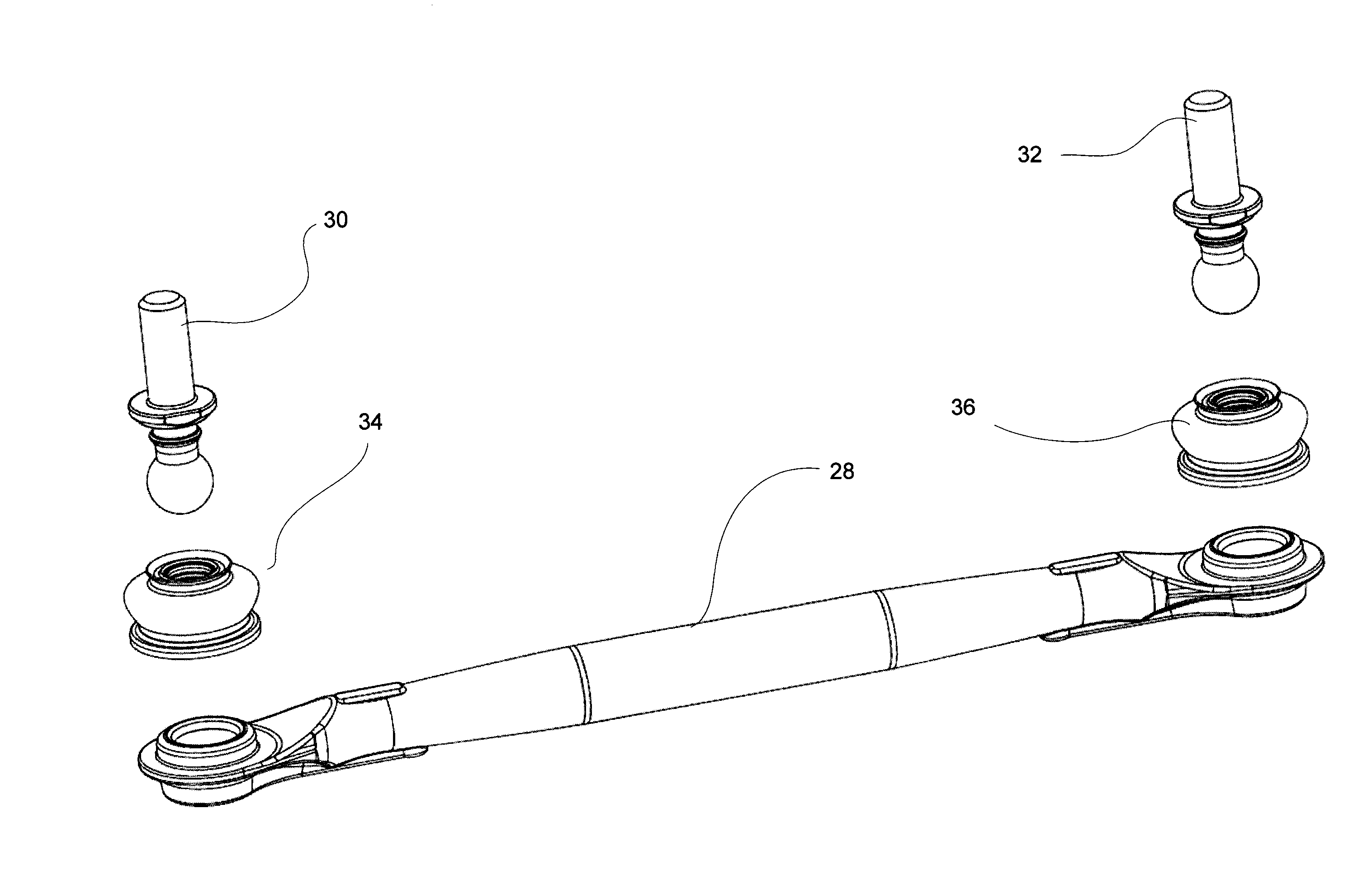
[0022]The stiffness of the endlink is important in that any bending or deflection reduces the precision with which the suspension, and therefore the vehicle, can be controlled.

[0023]Each wheel of a vehicle equipped with a MacPherson strut-type suspension typically features a single control arm attached to a stru...


PUM


Abstract

A suspension stabilizer endlink, affixed to a stabilizer bar and a vehicle suspension arm or strut, comprising a contoured shape and varying in size along the length of the endlink, with the largest cross-sectional area provided in the middle portion of the endlink and the smallest cross-sectional area provided at the ends of the endlink.

Description

BACKGROUND[0001]1. Field of the Disclosure[0002]The present disclosure relates to suspension stabilizer systems.[0003]2. Description of the Related Art[0004]Primary goals of vehicle suspension design may include optimizing individual tire traction, achieving a reasonable balance between all the tires, and arriving at an acceptable compromise between ride comfort and vehicle stability within a given cost constraint. One design consideration for four-wheeled vehicles is the degree of lateral weight transfer as the vehicle turns, and how to control that transfer as part of the vehicle design process.[0005]As a four-wheeled vehicle, for example an automobile, turns weight is transferred from the inside to the outside tires. Assuming equal static side-to-side weight distribution, more of a vehicle's weight is distributed over the left side tires as the vehicle travels through a right hand turn, and vice versa. The relationship of how much weight or vertical load is transferred from the t...

Claims


Application Information

Patent Timeline
Patent Type & Authority Applications(United States)
IPC IPC(8): B60G21/055
CPCB60G21/0551B60G7/001B60G7/005B60G21/055B60G2204/1224B60G2204/416B60G2206/11
Inventor STEINKAMP, KYLE G.WILSON, JAKIN C.
Owner TOYOTA MOTOR ENGINEERING & MANUFACTURING NORTH AMERICA
Why Eureka
Try Eureka