
Electrochemical descaling by pulsed signal reversal

a pulsed signal and descaling technology, applied in lighting and heating apparatus, heating types, immersion heating arrangements, etc., can solve the problems of scale formation on heating elements, reduced steam generation devices, and inability to be used anymore, so as to prevent or reduce scaling and prevent or reduce the formation of scale on heating elements

Active Publication Date: 2019-06-04
VERSUNI HLDG BV
View PDF20 Cites 0 Cited by
  • Summary
  • Abstract
  • Description
  • Claims
  • Application Information

AI Technical Summary

Benefits of technology

This method substantially prevents scale formation and corrosion on heating elements, allowing for decalcification and maintaining the integrity of the electrodes without the need for continuous chemical addition or complex constructions, while being adjustable to prevent corrosion without amplitude increase.

Problems solved by technology

A problem with such devices is that scale may form on the heating elements that are in contact with the water.
If the scale is not (periodically) removed clogging up may occur, as a result of which the performance of the steam generation device may decrease and, eventually, the steam generation device may not be fit to be used anymore.
However, chemicals are added into the water which may be a drawback, for instance when water is (also) meant to be potable.
Physical methods to prevent scale formation have also been claimed but these may have a less clear working principle and the efficacy may sometimes even be doubtful in some cases.

Method used


Image

  • Electrochemical descaling by pulsed signal reversal
  • Electrochemical descaling by pulsed signal reversal
  • Electrochemical descaling by pulsed signal reversal

Examples


examples

Water Preparation

[0081]Stock solutions of CaCl2.2H2O (65.6 gr / ltr), MgSO4.7H2O (38 gr / ltr) and NaHCO3 (76.2 gr / ltr) were made. Standard hard water was made by mixing 50 gram of each stock solution into 9 liter of de-ionized water and adding up to 10 liter. The resulting water had a total hardness of 16.8 0DH and a temporary hardness of 11.2 0DH. Total hardness is defined as 2.8×2×[mmol / ltr Ca+mmol Mg / ltr]. Temporary hardness is defined as 2.8×[mmol HCO3− / ltr]

Corrosion Experiments (Low Temperature)

[0082]In the following examples the effect of various parameters is shown especially on the corrosion of the electrodes when the amplitude is increased. In a typical experiment two stainless steel electrodes (316 grade) of 2.5 and 6 mm diameter were immersed in a beaker filled with standard hard water. Water was heated to 75° C. and an electrical signal was applied across the electrodes. Current was run for 30 minutes and electrodes inspected visually.

experiment 1

[0083]A sinusoidal AC signal of 3V and 0.5 Hz was applied across the two electrodes. Severe corrosion occurred at both electrodes.

experiment 2

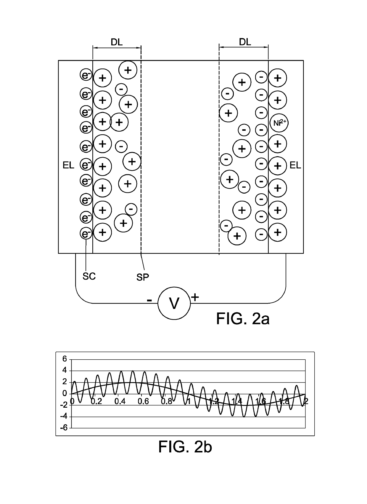
[0084]An AC signal of 3V and 0.5Hz was modulated with 100 Hz at 80% duty cycle and applied on the two electrodes as in previous experiment. After 30 min the electrodes were visually inspected. The small (2.5 mm) electrode showed a weak yellow cast while the 6 mm electrode was colorless.


PUM

PropertyMeasurementUnit
frequencyaaaaaaaaaa
frequencyaaaaaaaaaa
AC frequencyaaaaaaaaaa

Abstract

The invention provides a heater arrangement and method for heating a liquid, wherein the heater comprises a heating element, wherein the method comprises (i) heating the liquid in the heater wherein the heating element is in contact with the liquid, and (ii) applying a potential difference between the heating element and a counter electrode, wherein the potential difference has an AC component whereby the potential difference varies with an AC frequency in the range of 0.01-100 Hz and wherein the potential difference is applied with a cycle time, wherein the potential difference has a sign during a first part of the cycle time that is opposite of the sign of the potential difference during a second part of the cycle time, and wherein during one or more of the first part of the cycle time and the second part of the cycle time, the potential difference temporarily changes sign.

Description

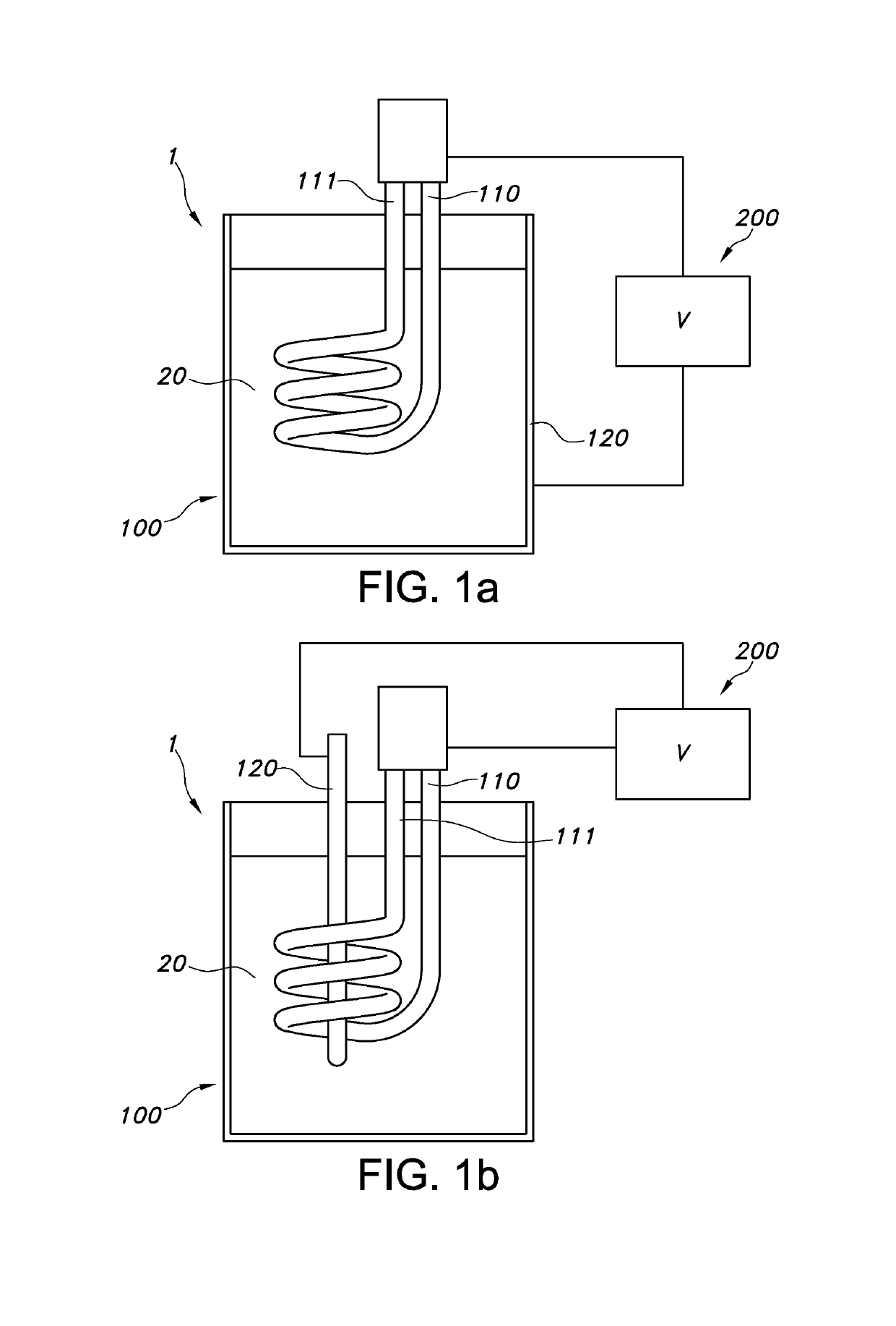
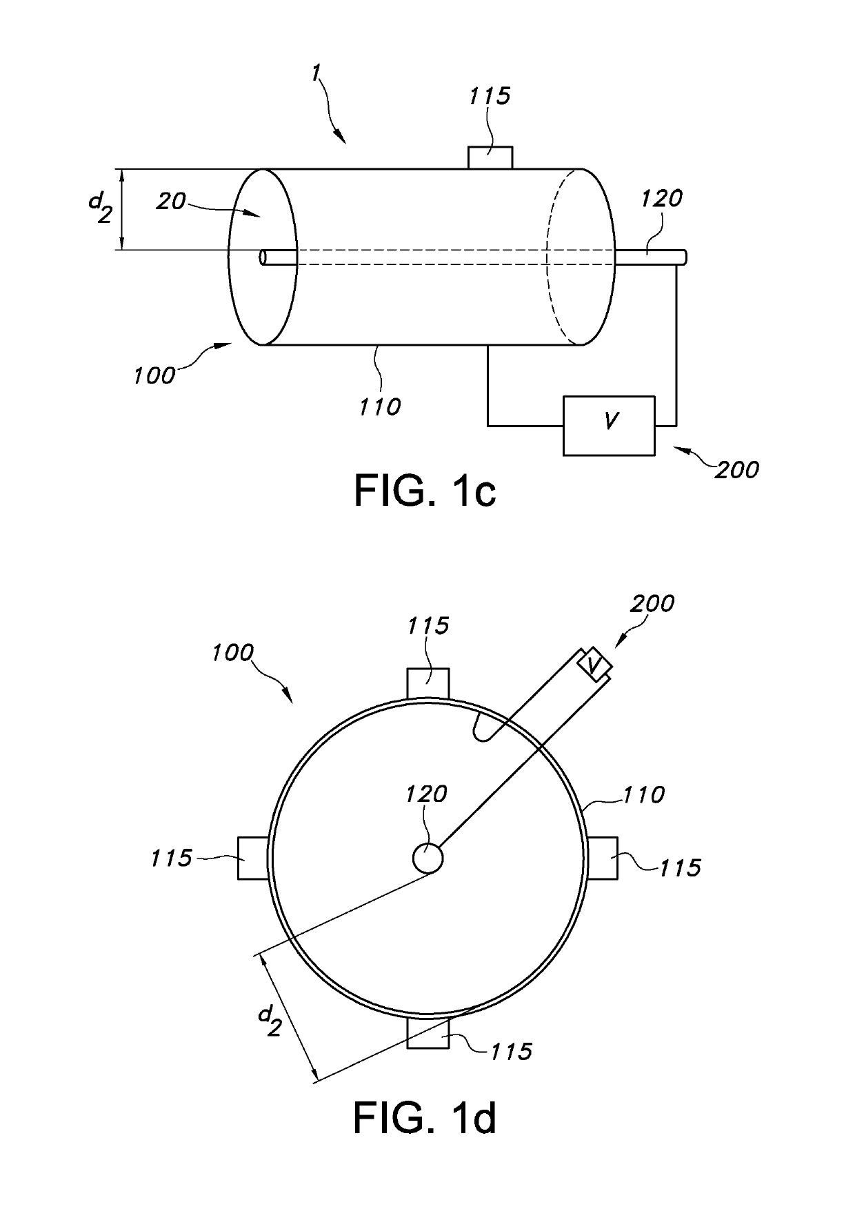
[0001]This application is the U.S. National Phase application under 35 U.S.C. § 371 of International Application No. PCT / IB2014 / 060204, filed on Mar. 27, 2014, which claims the benefit of U.S. Provisional Application 61 / 807,364 filed Apr. 2, 2013. These applications are hereby incorporated by reference herein.FIELD OF THE INVENTION[0002]The invention relates to a method for heating a liquid, especially water, a (water) heating arrangement for applying such method as well as to an electronic device comprising such (water) heating arrangement.BACKGROUND OF THE INVENTION[0003]Water heating devices are applied in all kind of applications, such as steam irons, electric kettles, hot drink vending machines, etc. A problem with such devices is that scale may form on the heating elements that are in contact with the water.[0004]During operation of for instance a steam generation device, water is supplied to a part of the water infrastructure where it is heated, such as in the (external) boil...

Claims


Application Information

Patent Timeline
Patent Type & Authority Patents(United States)
IPC IPC(8): F24D19/00H05B3/78H05B1/02C02F1/46F24H9/00F24H1/20F24H1/10F24H1/00C23F13/20A47J31/60A47J27/21C02F1/461
CPCH05B1/02A47J31/60C02F1/4602C02F1/4618C23F13/20F24D19/0092F24H1/0018F24H1/101F24H1/106F24H1/202F24H9/0047H05B1/0269H05B3/78A47J27/21025H05B2203/021C02F2201/4613C02F2201/46155C02F2201/46175C02F2303/08C02F2303/22C02F2307/12F24D2200/08F24H2250/02F24H2250/10H05B3/60F24H9/455
Inventor DE VRIES, JOHANNES HOTZE BERNHARDWIELSTRA, YTSENMULDER, BERNARDO ARNOLDUSDE VRIES-ARENTSEN, NIENKE CORNELIE
Owner VERSUNI HLDG BV
Learn More