
Method and apparatus for operating a germicidal UV device with a programmable logic controller and a bluetooth low energy solution

a technology of programmable logic controller and germicidal uv device, which is applied in the direction of gas discharge lamp details, wireless commuication services, cooling/ventilation/heating modification, etc., can solve the problems of inability to reproduce, increase maintenance costs, and the use of multiple germicidal lamps. , the application of a very high-output germicidal lamp, is not without difficulties

Active Publication Date: 2019-06-25
ULTRAVIOLET DEVICES
View PDF1 Cites 9 Cited by
  • Summary
  • Abstract
  • Description
  • Claims
  • Application Information

AI Technical Summary

Benefits of technology

[0013]It is highly desirable to be able to utilize germicidal lamps and in particular very high output germicidal lamps for air and surface applications. The present invention discusses a novel approach to utilize the very high UVC output of germicidal amalgam lamps in UVC disinfection devices in air and surface applications by providing a means to reduce and / or control the temperature of the amalgam spot(s) thus allowing the lamp to operate in its ideal operating range.

Problems solved by technology

UVC devices employ one or more lamps emitting a spectral wavelength output of approximately 254 nm which disrupts the DNA structure of the micro-organisms, rendering them harmless and unable to reproduce.
The use of multiple germicidal lamps increases expenses, as well as maintenance.
However, applying a very high output germicidal lamp, particularly in air, is not without difficulties.
Typically, it is from 80 degrees C. to 140 degrees C. However, the higher temperatures occurring at high loading of the lamp may cause the temperature of the amalgam to exceed the maximum operating temperature.
This is most likely the reason that most applications of very high output lamps are limited to water treatment applications only.
Currently, there are little or no applications of very high output lamps in ambient air.
The amalgam may move out of position and could make contact with an electrode and cause possible shorting or ineffective operation of the lamp.
Solidified amalgam material at a position within the discharge path, for example, may become too hot at a later stage of the lamp use, i.e. the amalgam temperature will become outside its temperature range.
When the amalgam is operating outside its ideal temperature range, this results in too high a mercury vapor pressure and hence reduces the lamp efficiency.
If the system design and application do not allow the amalgam to get into their proper operating temperature range, the lamp will have very low UV output and tend to be quite unstable.
However, due to the susceptibility of the amalgam to melt when the temperature exceeds the operating range, the use of germicidal amalgam lamps has been almost exclusively limited to water or liquid disinfection applications, wherein the amalgam lamps are constantly submerged in water or liquids, allowing the lamps to operate in the ideal temperature range.

Method used


Image

  • Method and apparatus for operating a germicidal UV device with a programmable logic controller and a bluetooth low energy solution
  • Method and apparatus for operating a germicidal UV device with a programmable logic controller and a bluetooth low energy solution
  • Method and apparatus for operating a germicidal UV device with a programmable logic controller and a bluetooth low energy solution

Examples


Embodiment Construction

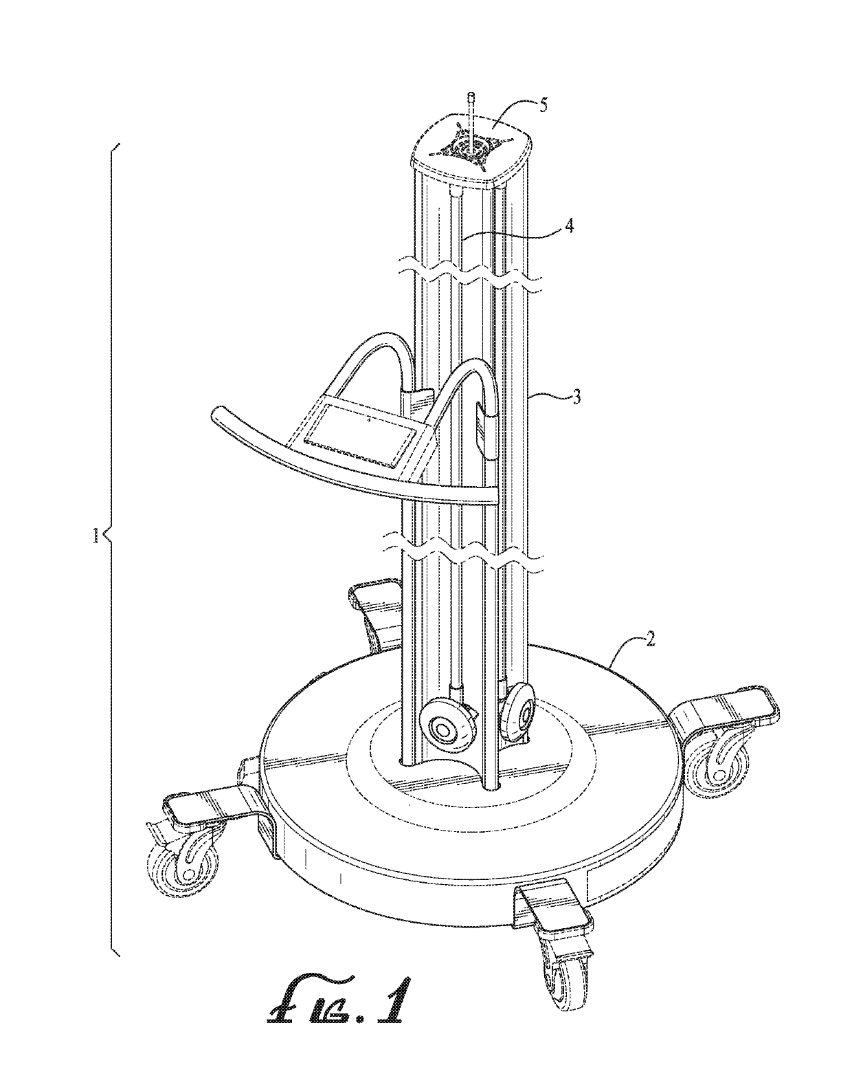
[0051]Referring to FIG. 1, a typical device 1 for the UV disinfection of air or surfaces is shown. The basic elements of the device are a base 2, a support, in this case, acting also as a conduit 3 and an opening 5 for the exit of air. One or more lamps 4 are installed around the support or conduit 3.

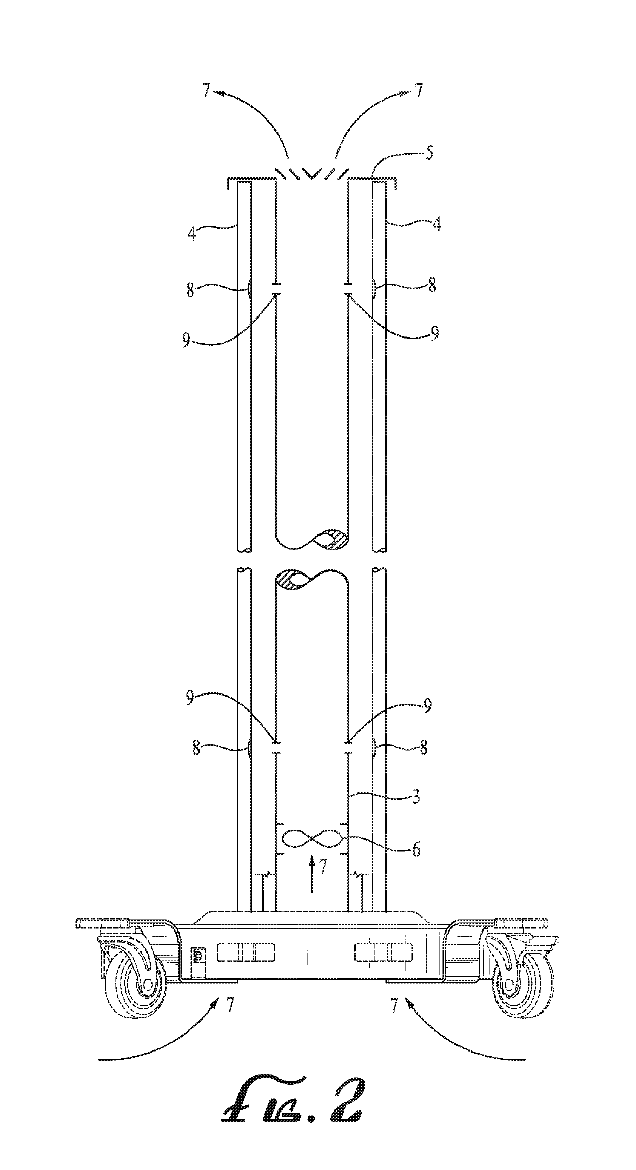
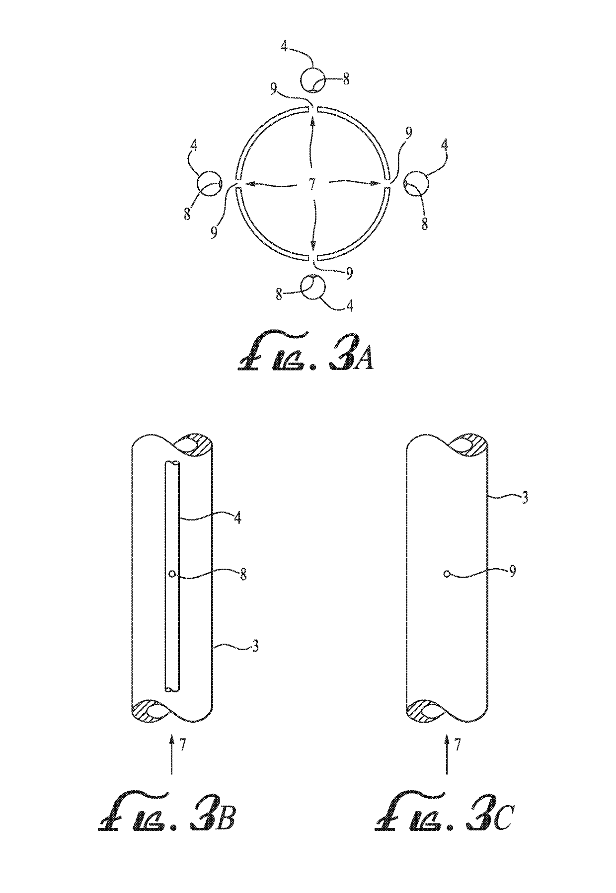
[0052]FIG. 2 shows the typical device 1, in cross section. An air moving device 6, including without limitation a fan or blower, is installed in the conduit 6 or may be installed in the base 2. The air moving device 6 causes air 7 to move into the conduit 3 and much of the air to exit through opening 5. Orifices, openings or holes 9 of a specific pre-determined diameter are placed in the conduit 4 at a strategic point selected to direct the air 7 through the orifices 9 to an area near or at the critical spot or points 8 (including mercury spot or amalgam spot, which contains mercury) on the lamp 4.

[0053]In another embodiment, not shown, the opening 5 may be omitted allowing all the air ...


PUM

PropertyMeasurementUnit
wavelength rangeaaaaaaaaaa
spectral wavelengthaaaaaaaaaa
UVC wavelengthaaaaaaaaaa

Abstract

This invention employs a computer system or a programmable logic controller (computer) with a specific wireless communication protocol (BLE) to allow for remote connectivity of the germicidal UV device to display the status of the disinfection cycle and to operate the device and send and transfer data wirelessly to the Cloud via the BLE interface. A dose sensitive coupon, which can undergo color change in response to UV dosage, can also be used.

Description

PRIORITY CLAIM[0001]This application is a continuation in part of U.S. patent application Ser. No. 15 / 044,103, filed on Feb. 15, 2016, and issues as U.S. Pat. No. 9,666,424 on May 30, 2017, which is a continuation in part of U.S. patent application Ser. No. 14 / 325,357, filed on Jul. 7, 2014, and issued as U.S. Pat. No. 9,265,174 on Feb. 16, 2016, which claims the benefit of U.S. Provisional Patent Appl. No. 61 / 895,010, filed on Oct. 24, 2013; this application also claims the benefit of U.S. Provisional Patent Appl. No. 62 / 220,932, filed on Sep. 18, 2015; this application is also related to U.S. Design Pat. D684,671, which was issued on Jun. 19, 2013; this application is also related to U.S. Provisional Patent Appl. No. 61 / 761,670, filed on Feb. 6, 2013 and U.S. patent application Ser. No. 14 / 172,886, filed on Feb. 4, 2014; all mentioned applications and patents are incorporated by reference in entirety.BACKGROUND OF THE INVENTION[0002]The effectiveness of germicidal ultraviolet (UV-...

Claims


Application Information

Patent Timeline
Patent Type & Authority Patents(United States)
IPC IPC(8): A61L2/10A61L9/20H05K7/20H04W4/80H01J61/52H04W4/00
CPCA61L2/10A61L9/20H01J61/52H05K7/20436H04W4/80
Inventor VELOZ, PETERMATHUR, ASHISHSHOSTAK, ALEKSANDRHAYES, RICHARDWITHAM, DAVIDBABKES, MITCHBETANCOURT, FILIBERTOROTKOP, LEVTYRRELL, STUARTMACLAY, WALTBROWN, DAN
Owner ULTRAVIOLET DEVICES
Learn More