Apparatus and method for attaching and testing a sleeve with a coupling end to a steel wire

a technology of coupling end and apparatus, which is applied in the direction of mechanical apparatus, ropes and cables for vehicles/pulleys, manufacturing tools, etc., can solve the problems of cumbersome testing, and achieve the effect of convenient reliable testing of the connection

Active Publication Date: 2019-06-25
WIRETEKNIK AB
View PDF10 Cites 0 Cited by
  • Summary
  • Abstract
  • Description
  • Claims
  • Application Information

AI Technical Summary

Benefits of technology

[0006]It is an object of the present invention to provide an apparatus that facilitates reliable testing of the connection between a sleeve and a steel wire to which it is attached. A further object is to provide a multifunctional apparatus which is adapted to perform both attachment of a sleeve to a steel wire and testing of said attachment. These objects are achieved by the inventive apparatus as described and claimed herein.
[0008]The inventive apparatus offers the possibility of attaching and verifying the thus achieved attachment within the same machine. Further, the simplicity of the apparatus and its manageable size makes it possible to bring the apparatus to installations where the fixation of sleeves to steel wires or the like needs to be verified. Further, if needed, fixation of a new sleeve to a steel wire may also be achieved on location.

Problems solved by technology

Such testing is cumbersome and either necessitates moving of the steel wire to a testing apparatus or installing of a cumbersome testing apparatus on location.

Method used


Image

  • Apparatus and method for attaching and testing a sleeve with a coupling end to a steel wire
  • Apparatus and method for attaching and testing a sleeve with a coupling end to a steel wire

Examples


Embodiment Construction

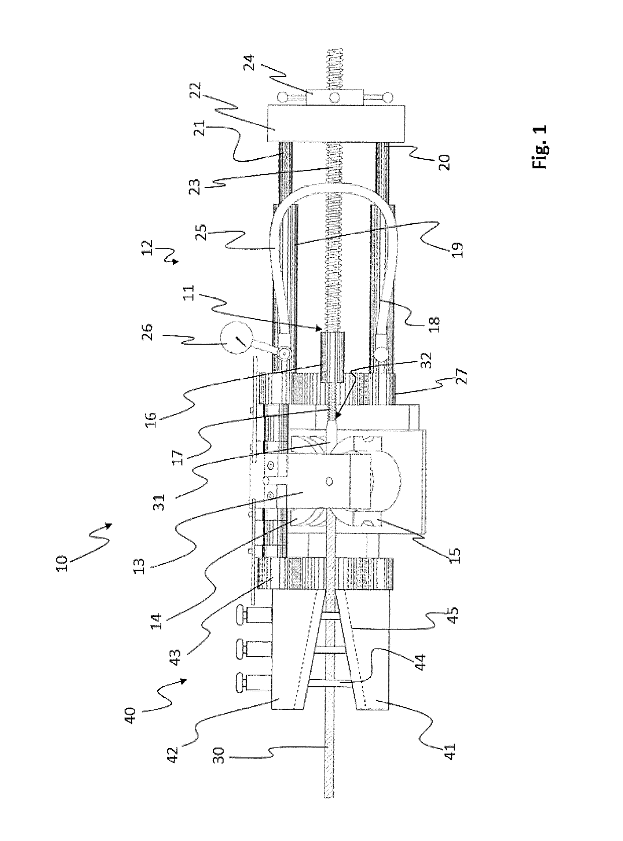
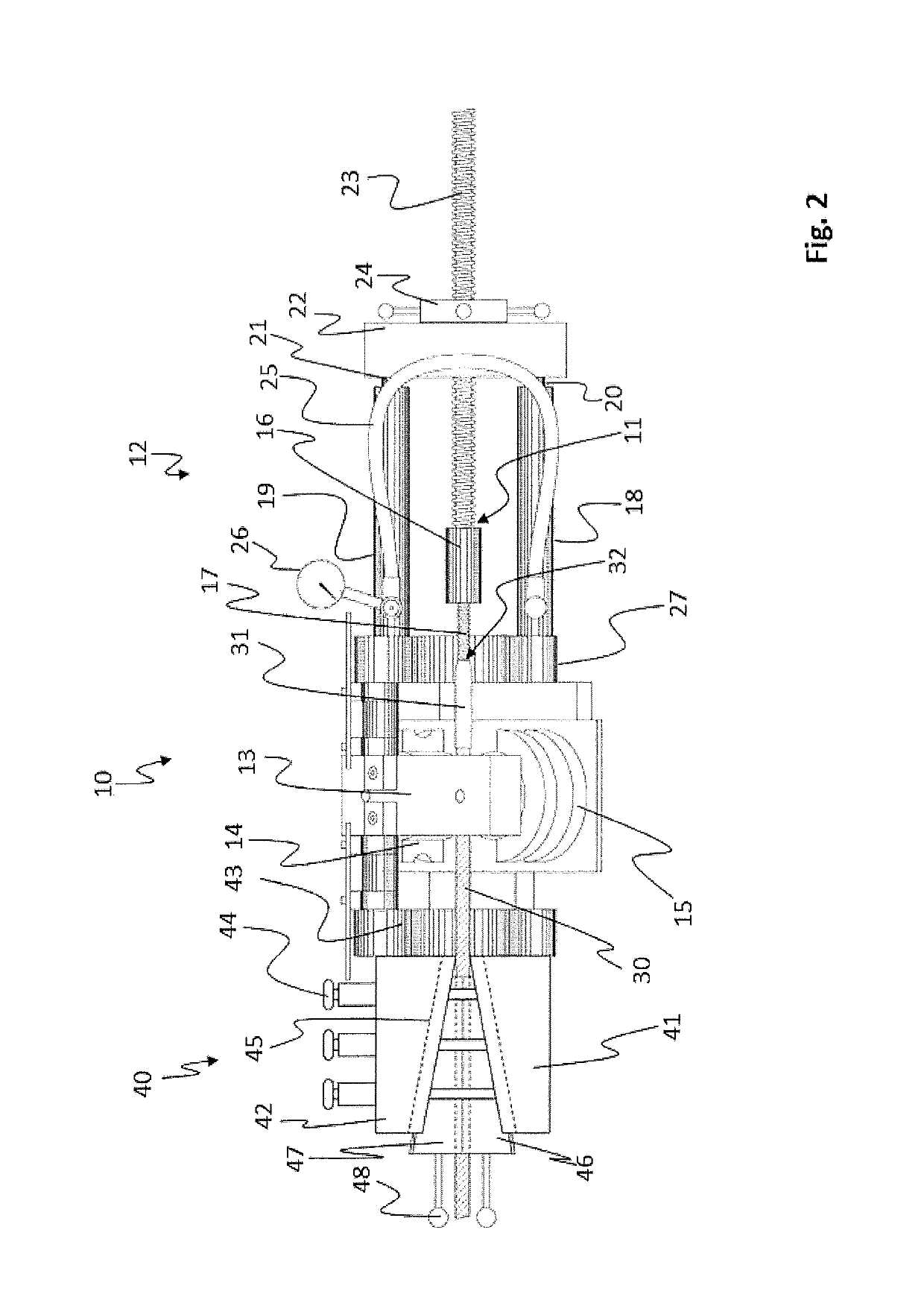
[0019]In FIG. 1 and apparatus 10 for attaching a sleeve 31 to a steel wire 30 by swaging is shown. The sleeve includes a coupling end 32 for facilitating handling of the steel wire 30. The apparatus comprises an attachment piece 16 arranged to connect to the coupling end 32 of the sleeve 31. A pulling arrangement 12 is connected to the attachment piece 16 via a pulling end 11.

[0020]In the shown embodiment the attachment piece 16 has a first end comprising a threaded bore for attachment to the pulling end 11, and a second opposed end comprising a screw 17 for insertion into the coupling end 32, in the form of a threaded bore, of the sleeve 31. Sleeves may have different shapes and different types of coupling ends 32 for attachment and therefore different attachment pieces may be needed in order to correctly connect to a specific sleeve. The attachment piece 16 should therefore be adapted to the specific coupling end 32 of the sleeve 31 that is to be attached to the steel wire 30. The...


PUM

PropertyMeasurementUnit
traction forceaaaaaaaaaa
frictionaaaaaaaaaa
pulling forceaaaaaaaaaa

Abstract

Apparatus for attaching a sleeve comprising a coupling end to a steel wire. The apparatus comprises a pulling end arranged to connect to a sleeve to be attached to a steel wire, a pulling arrangement connected to the pulling end and being configured to pull a sleeve connected to the pulling end, a swaging arrangement comprising two opposed swaging rolls adapted to crimp the sleeve to a close press fit around a loose end of a steel wire. The apparatus further comprises a testing arrangement for testing the strain capacity of the attachment of a sleeve to a steel wire, the testing arrangement including a holding unit configured to effectively hold a portion of the steel wire fixed and allowing the pulling arrangement to pull the sleeve attached to a wire held fixed in the holding unit in order to verify the attachment.

Description

TECHNICAL FIELD[0001]The invention relates to an apparatus for attaching a sleeve to a steel wire or the like by swaging. Specifically, the invention relates to such an apparatus that is also adapted to test and verify the attachment of the sleeve to said steel wire.BACKGROUND[0002]Steel wires are used in a wide variety of applications and often a sleeve with a coupling end is attached to at least one end of the steel wire for facilitating handling of the steel wire. Such sleeves are advantageously attached to the steel wire by means of a swaging machine. Different types of swaging machines exist and they may typically be divided in different categories depending on the means for creating the pulling force. Hence, there are inter alia electric apparatuses, combustion driven apparatuses and hydraulic apparatuses.[0003]An advantageous such apparatus is described in GB 2053760 B, in which a pulling arrangement is provided to achieve the needed pulling force. This document describes the...

Claims


Application Information

Patent Timeline
Patent Type & Authority Patents(United States)
IPC IPC(8): F16G11/02B21F15/00B21H1/22B23P11/00B23P19/04D07B9/00G01N3/10D07B7/02
CPCG01N3/10B21F15/00B21H1/22B23P19/047F16G11/025B23P11/005D07B9/00D07B7/027
Inventor OTT, JESPER
Owner WIRETEKNIK AB
Why Eureka
Try Eureka