
Manned and unmanned aircraft

a technology of unmanned aircraft and pilots, applied in emergency equipment, transportation and packaging, board measures, etc., can solve the problems of design commonality, mechanical disadvantage of the drive system, and craft rolling or flipping on contact, etc., and achieves high stability, maneuverability, and mechanical efficiency.

Active Publication Date: 2019-07-09
DRONEXUS AERO LLC
View PDF22 Cites 4 Cited by
  • Summary
  • Abstract
  • Description
  • Claims
  • Application Information

AI Technical Summary

Benefits of technology

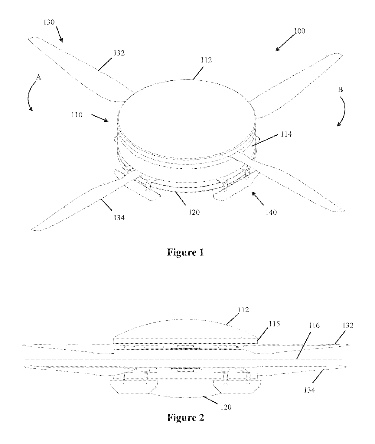
[0006]Accordingly, it is an object of the invention to provide an aircraft that is highly stable, maneuverable, and mechanically efficient, and especially one that can be utilized as a helicopter in both a manned and unmanned variant and avoids the dangers involved during a mechanical failure such as current industry standard helicopters which are inherently top-heavy platforms and current industry standard quad copters which become unstable and crash if any one of the blades / motors fail.
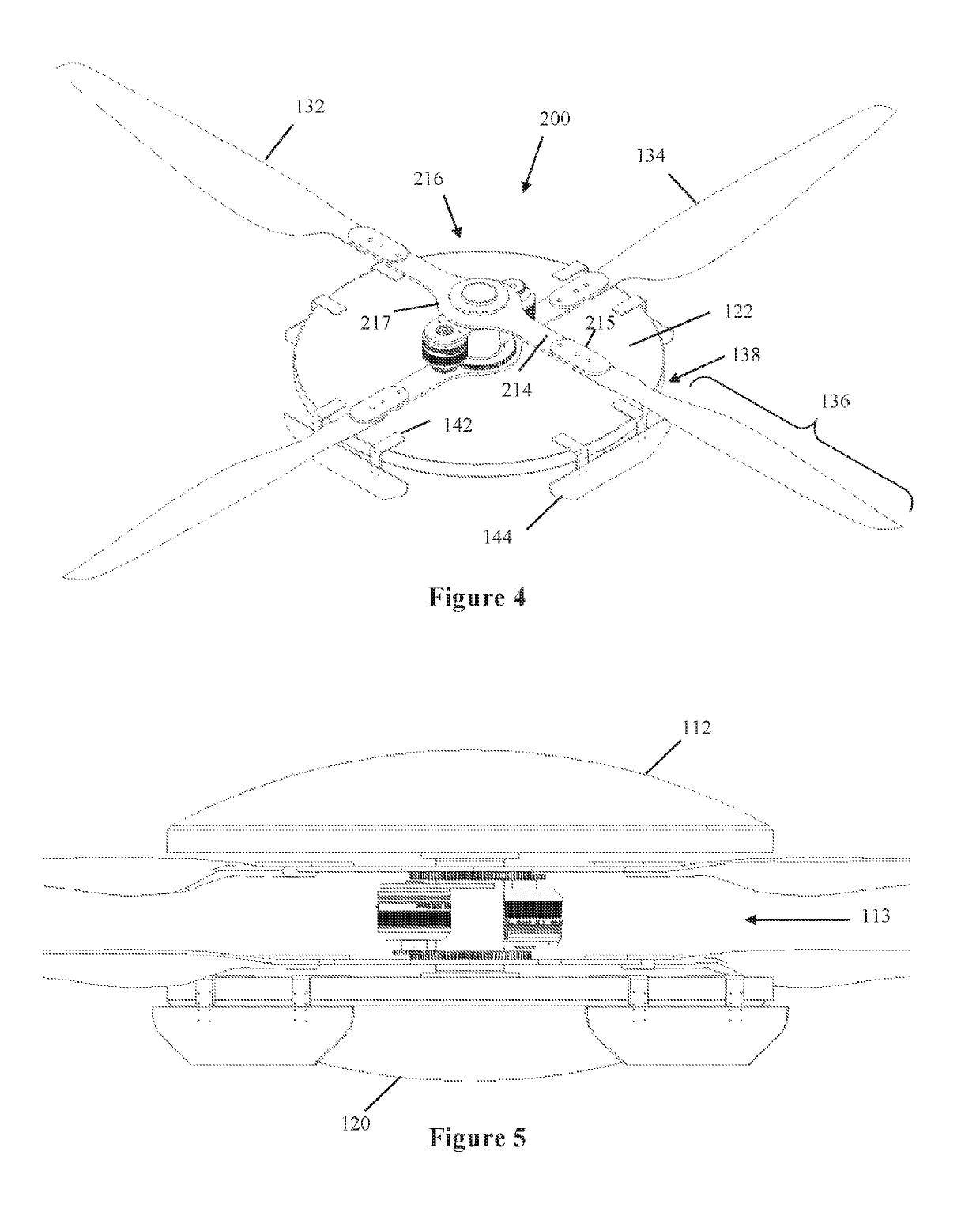
[0007]This invention changes the historical concept of helicopters by modifying the entire mechanical and lift structure mechanisms. The present invention is a circular saucer-shaped craft and is related to U.S. Pat. Nos. 9,555,879, 9,840,323, D798,221, and 9,896,196, as well as U.S. Publ. No. 2018 / 0244378, the entire contents of which are hereby incorporated by reference. The invention has a series of main lift and counter rotation blades emanating from the craft's horizontal center line and having a drive system at a point between the craft's outer periphery and its' center vertical axis. Such a drive configuration away from the center vertical axis creates an inherent torque advantage allowing for the use of a variety of blades without the need for a discrete transmission as used in current industry standard helicopters. The design and configuration allows for the craft to be a variety of sizes and the flexibility to be configured in either a manned or UAV variant.
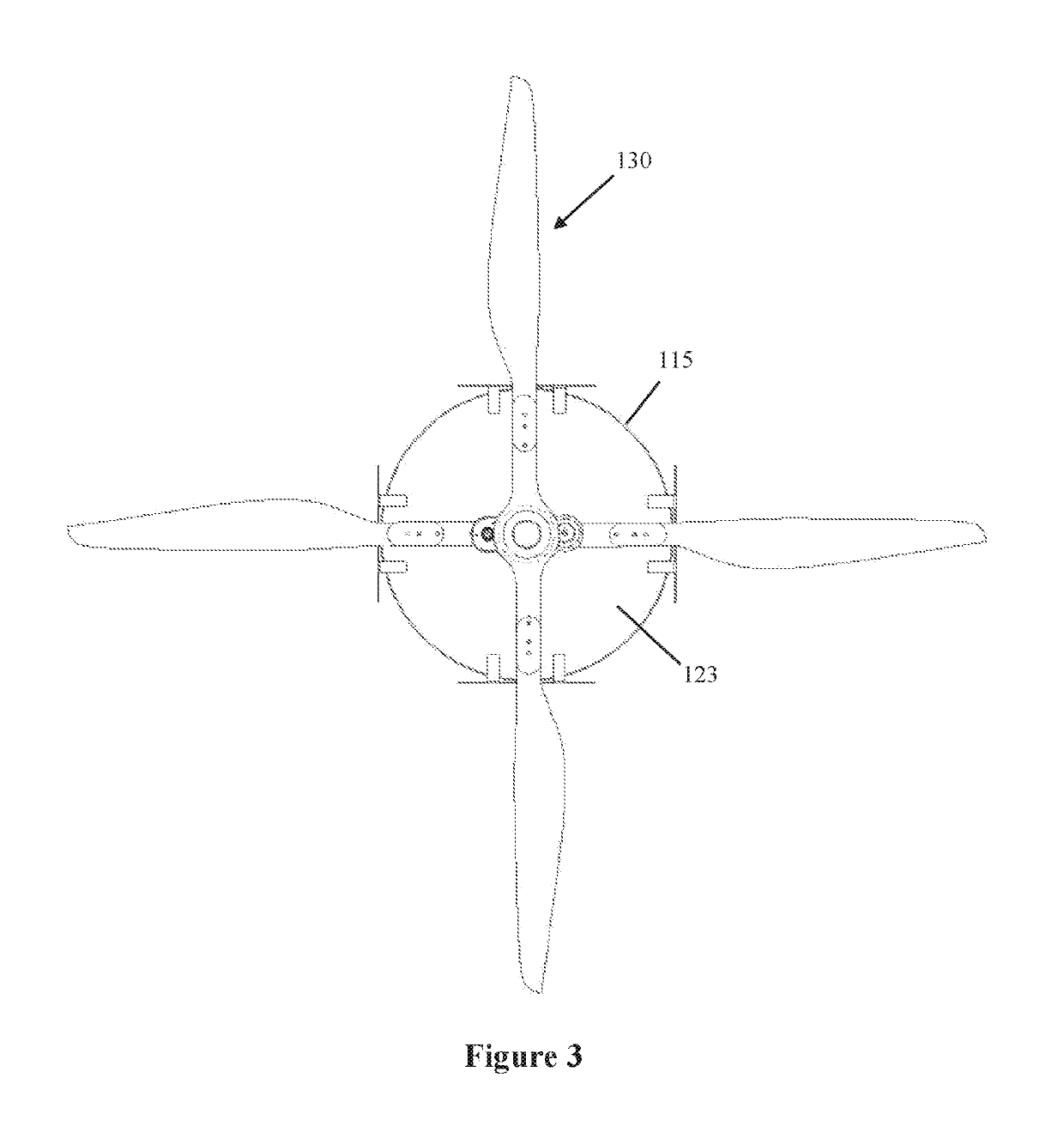
[0008]An aircraft is provided that has the rotor blades at the outer periphery of the craft and at or about the horizontal centerline of the craft. Accordingly, the aircraft is highly aerodynamic since the air flow generated by the blades is unobstructed by the rest of the aircraft, including the fuselage, except with respect to the flaps (discussed in more detail below). That creates greater thrust, lift and higher efficiency. Much shorter and wider rotor blades are utilized, and the angle of attack is permanently fixed at a predetermined constant lift position with the motors affixed in a position away from the craft's center vertical axis which include a shaft gear significantly smaller than the blade drive gear creating a substantial torque advantage. The rotor blades are coupled with the drive system at the general center of mass of the craft. The invention alleviates the need for a blade tilt system and achieves greatly enhanced mechanical advantage, including increased torque at the blade's drive point. Such a drive configuration is offset from the immediate center axis location, creating a distinct torque advantage to the lift blades.

Problems solved by technology

The drive system is at a mechanical disadvantage since it is positioned at the vertical axis of rotation, requiring a high torque or a complex transmission to provide ample RPMs for the greatly elongated and narrow blades to achieve lift.
However, this creates a top-heavy platform, and many helicopter crashes result in the craft rolling or flipping on contact.
This configuration / design commonality has an inherent weakness.
If any one of the motor / propeller assemblies fail, the drone / UAV craft will become unstable and experience uncontrollable flight.

Method used


Image

  • Manned and unmanned aircraft
  • Manned and unmanned aircraft
  • Manned and unmanned aircraft

Examples


Embodiment Construction

[0018]In describing a preferred embodiment of the invention illustrated in the drawings, specific terminology will be resorted to for the sake of clarity. However, the invention is not intended to be limited to the specific terms so selected, and it is to be understood that each specific term includes all technical equivalents that operate in similar manner to accomplish a similar purpose. Several preferred embodiments of the invention are described for illustrative purposes, it being understood that the invention may be embodied in other forms not specifically shown in the drawings.

[0019]Turning to the drawings, FIGS. 1-7 show an aircraft 100 in accordance with one preferred embodiment of the invention. The aircraft 100 includes a main housing or body 110, blades 130, and a drive system 200.

[0020]The main body 110 has an upper body portion 112 which includes a top saucer-dome assembly and a lower body portion 120 which likewise includes a saucer-dome. The upper and lower body porti...


PUM


Abstract

A manned or unmanned aircraft has a main body with a circular shape and a circular outer periphery. One or more rotor blades extend substantially horizontally outward from the main body at or about the circular outer periphery. In addition, one or more counter-rotation blades extend substantially horizontally outward from said main body at or about the circular outer periphery, but vertically offset from the main rotor blades.

Description

RELATED APPLICATIONS[0001]This application is a continuation of application Ser. No. 16 / 192,330, filed on Nov. 15, 2018, which is a continuation-in-part of application Ser. No. 15 / 883,781, filed Jan. 30, 2018, which is a continuation of application Ser. No. 15 / 600,296, filed May 19, 2017, now U.S. Pat. No. 9,896,196, which is a continuation-in-part of application Ser. No. 15 / 058,708, filed Mar. 2, 2016, now U.S. Pat. No. 9,840,323, which is a continuation-in-part of application Ser. No. 14 / 712,062, filed May 14, 2015, now U.S. Pat. No. 9,555,879, which claims priority to provisional Application No. 62 / 001,418, filed May 21, 2014. In addition, this application claims the benefit of U.S. Provisional Application No. 62 / 724,475, filed Aug. 29, 2018. The entire contents of the foregoing patents and applications are incorporated herein by reference.BACKGROUND OF THE INVENTIONField of the Invention[0002]The present invention relates to a manned aircraft as well as an unmanned or drone airc...

Claims


Application Information

Patent Timeline
Patent Type & Authority Patents(United States)
IPC IPC(8): B64C27/10B64D17/80B64C27/20B64C27/14B64D35/06B64C27/50B64D27/24B64C25/06B64C27/82
CPCB64C27/10B64C25/06B64C27/14B64C27/20B64C27/50B64D17/80B64D35/06B64D27/24B64D2211/00B64C2027/8272B64C2201/024B64C2201/027B64C2201/06Y02T50/50B64U10/13B64U30/24B64U10/60B64C39/024B64C27/12B64U10/10B64U30/20B64U50/13B64U50/19B64U50/34
Inventor KAISER, JAMESVATIS, WILLIAM
Owner DRONEXUS AERO LLC
Learn More