
Drone aircraft

a drone and aircraft technology, applied in the field of drone aircraft, can solve the problems of high horsepower requirement, low flight efficiency, and mechanical disadvantage of the drive system, and achieve the effect of avoiding mechanical failure dangers, high stability, and maneuverability

Active Publication Date: 2017-12-12
DRONEXUS AERO LLC
View PDF16 Cites 9 Cited by
  • Summary
  • Abstract
  • Description
  • Claims
  • Application Information

AI Technical Summary

Benefits of technology

This invention is a new type of helicopter that is stable, easy to control, and mechanically efficient. It uses unique rotor blades that are positioned at the outer edge of the craft and are fixed at a specific angle, which allows for greater mechanical advantage and torque at the blade's drive point. This design eliminates the need for a blade tilt system and makes it safer to utilize in case of mechanical failure. Overall, this new helicopter has improved performance and reliability.

Problems solved by technology

The drive system is at a mechanical disadvantage since it is positioned at the vertical vertex of rotation, requiring a high horsepower requirement to provide ample RPMs for the greatly elongated and narrow blades to achieve lift.
However, this creates a top heavy platform, and many helicopter crashes result in the craft rolling or flipping on contact.
This configuration / design commonality has an inherent weakness.
If any one of the motor / propeller assemblies fail, the drone / UAV craft will become unstable and experience uncontrollable flight.

Method used


Image

  • Drone aircraft
  • Drone aircraft
  • Drone aircraft

Examples


Embodiment Construction

[0021]In describing a preferred embodiment of the invention illustrated in the drawings, specific terminology will be resorted to for the sake of clarity. However, the invention is not intended to be limited to the specific terms so selected, and it is to be understood that each specific term includes all technical equivalents that operate in similar manner to accomplish a similar purpose. Several preferred embodiments of the invention are described for illustrative purposes, it being understood that the invention may be embodied in other forms not specifically shown in the drawings.

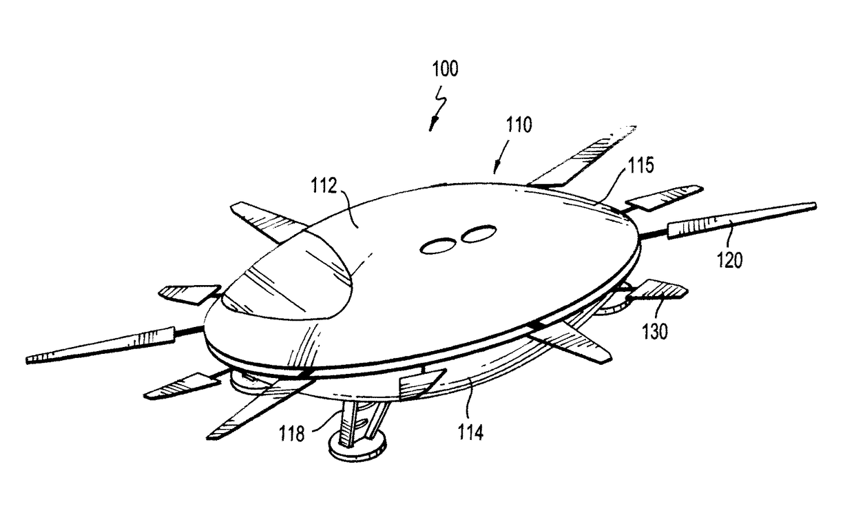
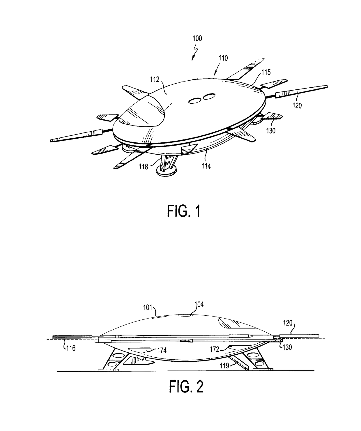
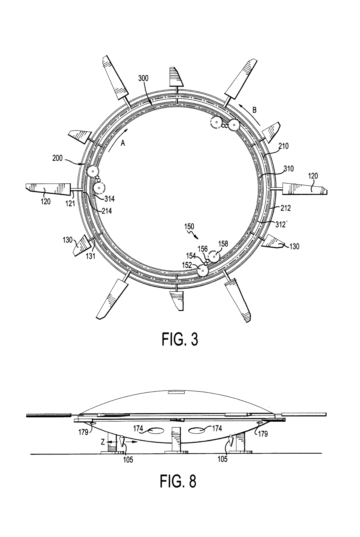
[0022]Turning to the drawings, FIGS. 1-2 shows an aircraft 100 in accordance with one preferred embodiment of the invention. The aircraft 100 includes a main housing or body 110, lift blades 120 and counter-rotation (or anti-torque) airfoil blades 130. The main body 110 has an upper body portion 112, a lower body portion 114, landing gear 118, and other usual features such as a cockpit, seating and windo...


PUM


Abstract

A drone aircraft has a main body with a circular shape and a circular outer periphery. One or more rotor blades extend substantially horizontally outward from the main body at or about the circular outer periphery. In addition, one or more counter-rotation blades extend substantially horizontally outward from said main body at or about the circular outer periphery, but vertically offset from the main rotor blades. The main rotor blades are connected to a first annular gear that rotates in a first direction and the counter-rotation blades rotate are connected to a second annular gear that rotates in a second direction that is opposite the first direction for anti-torque. Planetary gears simultaneously drive the first and second annular gear at about the same speed.

Description

RELATED APPLICATIONS[0001]This application is a continuation-in-part of U.S. Pat. No. 9,555,879, filed May 14, 2015, which claims the benefit of U.S. Provisional Application No. 62 / 001,418, filed May 21, 2014. The entire contents of those applications are incorporated herein by reference.BACKGROUND OF THE INVENTIONField of the Invention[0002]The present invention relates to a design for a drone aircraft. More particularly, the present invention relates to an aircraft, and particularly a drone, having a circular shape and blades positioned about the outer circumferential periphery.Background of the Related Art[0003]In current helicopters, a mechanically intricate system featuring a vertical drive shaft (mast) connected to an engine (gas piston or jet turbine) turn a series of blades that are very elongated and narrow. The rotational spinning of the blades about the mast at a sufficient RPM creates a lift factor consistent with the Bernoulli Principle. One way to move the helicopter f...

Claims


Application Information

Patent Timeline
Patent Type & Authority Patents(United States)
IPC IPC(8): B64C27/10B64C25/06B64D17/80B64C27/14B64D35/06
CPCB64C27/10B64C27/14B64D17/80B64C25/06B64D35/06B64C2201/024B64D27/24B64C15/14B64C2025/325Y02T50/60B64U10/10B64U50/19B64D27/026
Inventor KAISER, JAMES
Owner DRONEXUS AERO LLC
Learn More