Display device

a technology of display device and light guide plate, which is applied in the direction of planar/plate-like light guide, mechanical equipment, instruments, etc., can solve the problems of increasing apparatus size and increasing costs, and achieve the effect of reducing the amount of unnecessary second pattern display, positional deviation, and suppressing unnecessary second pattern display

Active Publication Date: 2019-07-09
PANASONIC INTELLECTUAL PROPERTY MANAGEMENT CO LTD
View PDF15 Cites 0 Cited by
  • Summary
  • Abstract
  • Description
  • Claims
  • Application Information

AI Technical Summary

Benefits of technology

[0028]In the display device according to the present disclosure, part of light incident on the light guide plate from the first light sources is reflected on the first reflection parts formed in the light guide plate to display the first pattern on the upper surface of the light guide plate. Part of light incident on the light guide plate from the first light sources reaches a light entrance surface opposite to the first light sources of the light guide plate, however, most of the reached light is reflected to the outside of the light guide plate by the slope formed in the opposite light entrance surface. Therefore, light reflected on the opposite reflection surface and propagating in the light guide plate again is reduced. Accordingly, the phenomenon in which the unnecessary second pattern is displayed can be suppressed.
[0029]Also in the display device according to the present disclosure, positional deviation is suppressed between the light guide plate and the light entrance, even when the light guide plate is deformed. Accordingly, the phenomenon in which intensities of light propagating inside the light guide plate varies according to light entrance positions can be suppressed even when proportions of light entering the light guide plate is changed according to deformed positions. Accordingly, the phenomenon in which light-emitting intensities of the pattern to be displayed varies according to display locations can be minimized and a beautiful display with a uniform light-emitting intensity can be realized.

Problems solved by technology

When plural light guide plates are necessary, costs are increased.
As space for setting plural light guide plates is also necessary, there is a problem that an apparatus will be increased in size.
Accordingly, there is a problem that the pattern “B” which is not desirable to be displayed is lightly displayed during display of the pattern “A”.
Accordingly, there is a problem that the pattern “A” which is not desirable to be displayed is lightly displayed during display of the pattern “B”.

Method used


Image

  • Display device
  • Display device
  • Display device

Examples


embodiment 1

[0054]FIGS. 1A, 1B, FIGS. 2A, 2B and FIG. 3 to FIG. 11 show embodiments of the present disclosure.

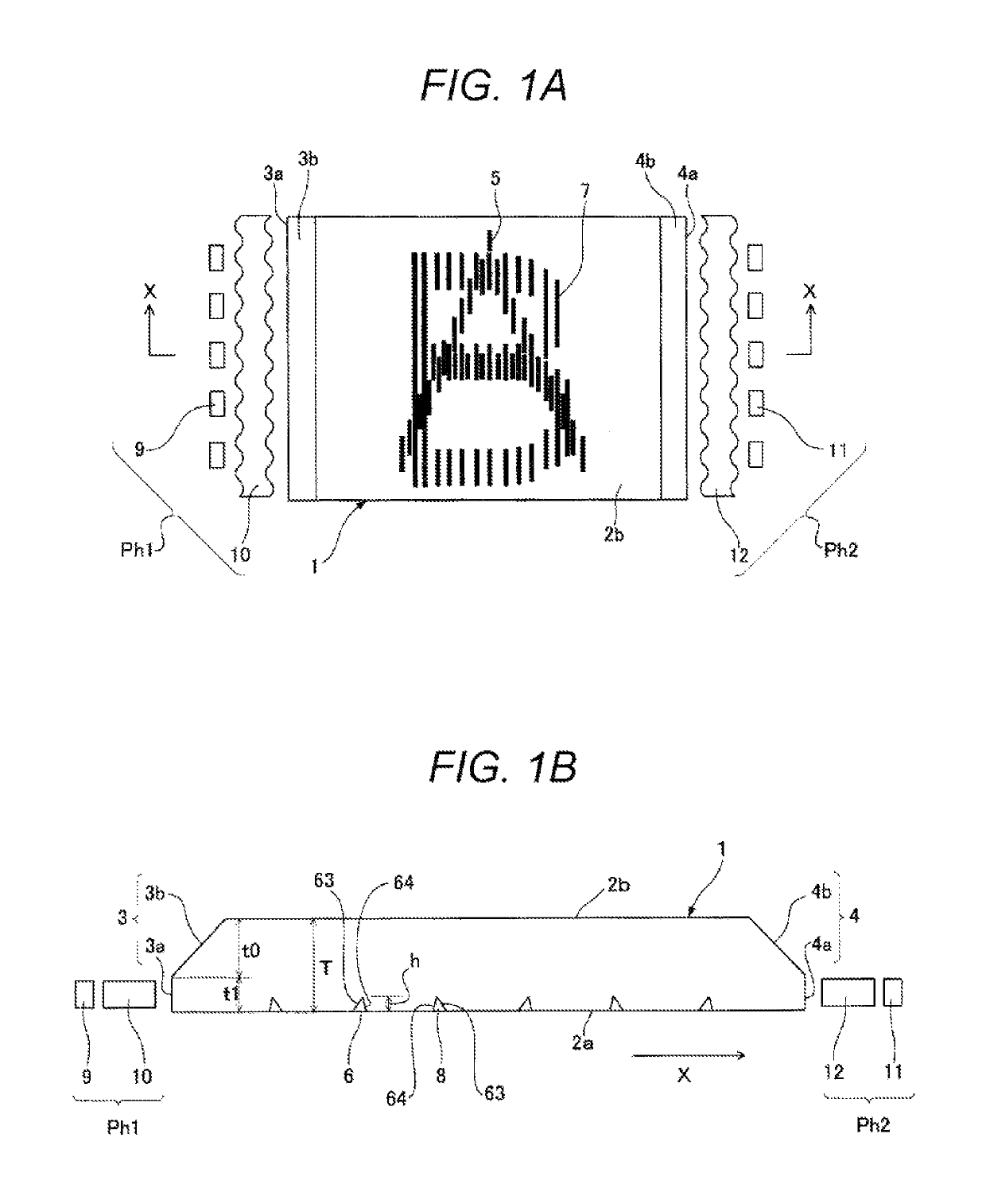
[0055]FIG. 1A shows a front view of a display device according to the present disclosure and FIG. 1B shows a cross-sectional view taken along X-X of FIG. 1A.

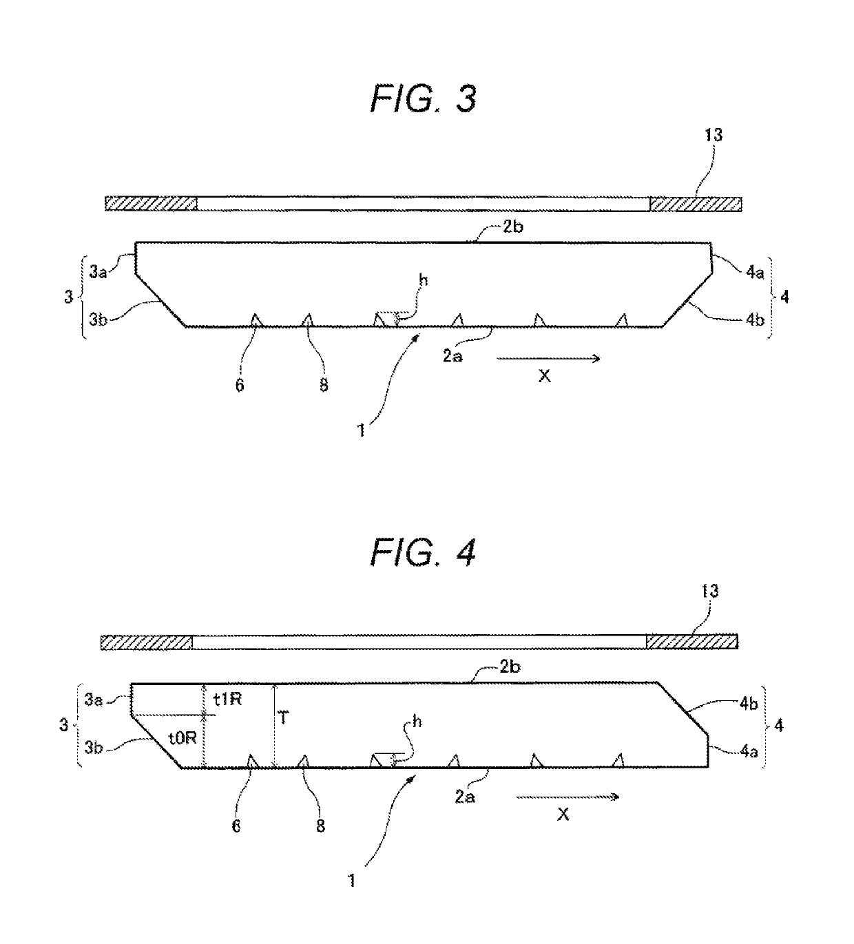
[0056]In a first side surface 3 and a second side surface 4 which face each other in an outer peripheral surface between a bottom surface 2a and an upper surface 2b of a flat light guide plate 1, the first side surface 3 includes a first incident surface 3a a lower end of which is connected to an outer periphery of the bottom surface 2a and which vertically rises and a first slope 3b which is positioned between an outer periphery of the upper surface 2b of the light guide plate 1 and an upper end of the first incident surface 3a and which is inclined toward the inside of the light guide plate 1. The first slope 3b is formed in the entire first side surface 3 in a lengthwise direction.

[0057]The second side surface 4 includes a second...

embodiment 2

[0084]FIG. 12, FIGS. 13A and 13B show Embodiment 2 of the present disclosure.

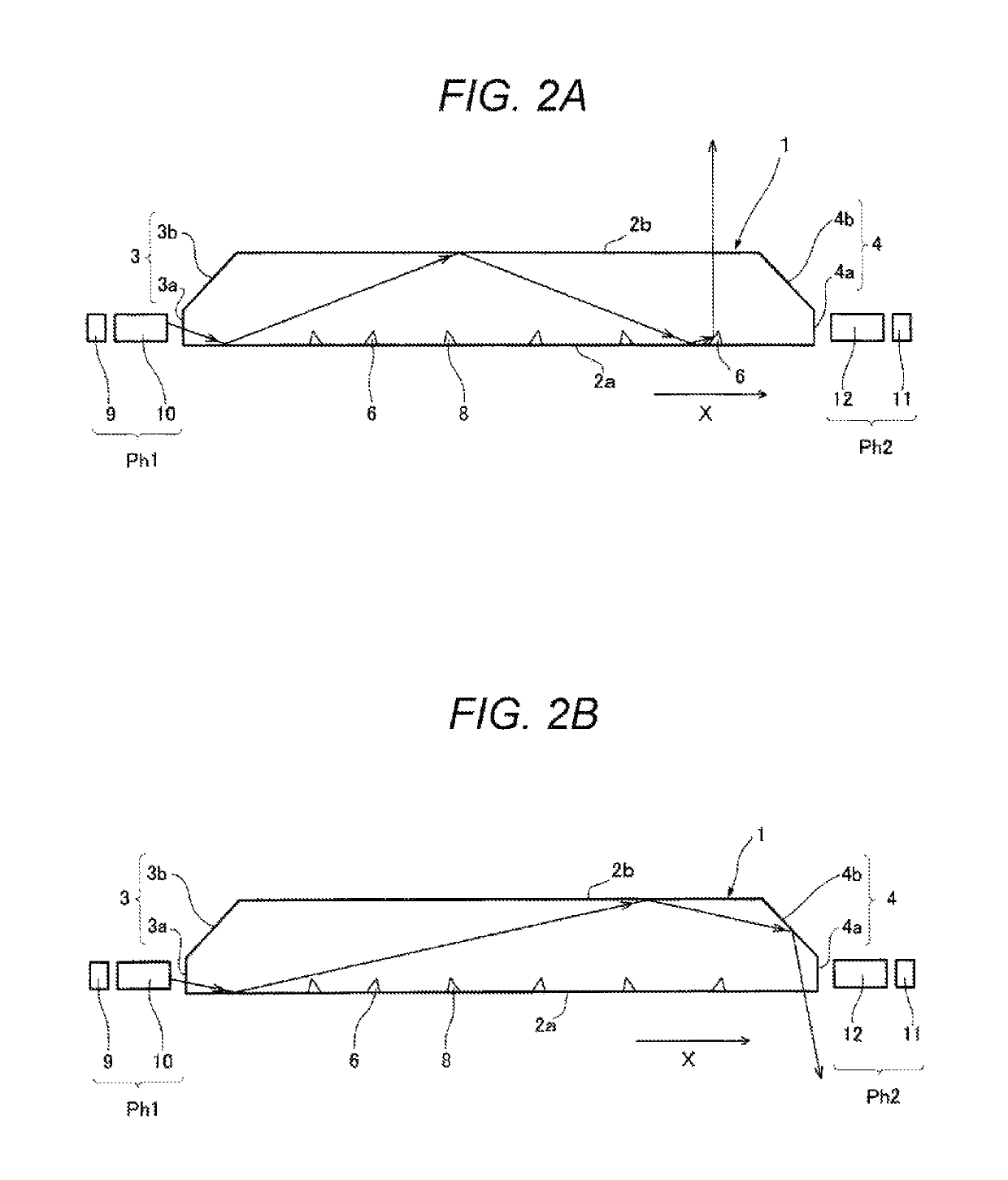
[0085]FIG. 12 shows a front view of a display device according to Embodiment 2 of the present disclosure, FIG. 13A shows a cross-sectional view taken along X-X of FIG. 12 and FIG. 13B shows a cross-sectional view taken along Y-Y of FIG. 12. In Embodiment 1, light is selectively incident on the first and second side surfaces 3 and 4 of the light guide plate 1 which face each other to thereby display the pattern 5 of “A” or the pattern 7 of “B” while switching between these patterns. In Embodiment 2, display is performed while not only switching between “A” and “B” but also switching between a pattern of “C” and a pattern of “D” by allowing light to be selectively incident on third and fourth side surfaces 23 and 24 of the light guide plate 1 which face each other.

[0086]The first and second side surfaces 3 and 4, the first and second reflection parts 6 and 8, and the first and the second light source units Ph...

embodiment 3

[0102]FIG. 14 shows a front view of a display device according to Embodiment 3 of the present disclosure, FIG. 15A shows a cross-sectional view taken along X-X of FIG. 14 and FIG. 15B shows a cross-sectional view taken along Y-Y of FIG. 14.

[0103]The light guide plate 1 including the first side surface 3 and the second side surface 4 facing each other is used in Embodiment 1. In a light guide plate 51 according to Embodiment 3, light is incident on the first side surface 3 from the first light source unit Ph1 and light is incident on the third side surface 23 adjacent to the first side surface 3 from the second light source unit Ph2. The first side surface 3 and the third side surface 23 of the light guide plate 1 are orthogonal to each other.

[0104]The first light source unit Ph1 is formed by light sources 9, such as light-emitting diodes, and a lens 10. The second light source unit Ph2 is formed by light sources 11, such as light-emitting diodes, and a lens 12. The lenses 10 and 12 ...


PUM

PropertyMeasurementUnit
refractive indexaaaaaaaaaa
transmittanceaaaaaaaaaa

Abstract

A display device includes a light guide plate, and light sources allowing light to be incident on a first side surface and a second side surface of the light guide plate. First incidental side surface light from the first light source is reflected to an upper surface side by first reflection parts formed on a bottom surface to display a first pattern, and second incidental side surface light from the second light source is reflected to the upper surface side by second reflection parts formed on the bottom surface to display a second pattern. Slopes are provided at parts of the first side surface and the second side surface of the light guide plate, and light reflected on a facing reflection surface and propagating in the light guide plate again is reduced by the slopes.

Description

TECHNICAL FIELD[0001]The technical field relates to a display device that switches and displays plural display information on one display area of one light guide plate.BACKGROUND[0002]A common display device using a light guide plate has an optical display structure in which light emitted from light-emitting devices such as light-emitting diodes is allowed to be incident on the inside of the light guide plate from a side surface in a bottom surface, an upper surface and the side surface of the light guide plate. The incident light is reflected in the inside of the light guide plate efficiently and is emitted from a display area on the upper surface of the light guide plate. On the bottom surface of the light guide plate, a large number of reflection parts having fine protruding shapes are formed for reflecting or refracting outgoing light efficiently.[0003]When the reflection part having the protruding shape is a conical reflection part 61 or a hemispheric reflection part 62 which p...

Claims


Application Information

Patent Timeline
Patent Type & Authority Patents(United States)
IPC IPC(8): F21V8/00G02F1/01G06F3/041
CPCG02B6/0028G02B6/003G02B6/0068G02F1/0105G02B6/0031G06F3/0412G02B6/0055G02B6/002G02B6/0036G02B6/006
Inventor TAKATA, KAZUMASATAKAMOTO, KENJIAGEMIZU, WAHEI
Owner PANASONIC INTELLECTUAL PROPERTY MANAGEMENT CO LTD
Why Eureka
Try Eureka