Method and apparatus for interrupting electrical conductivity through pipelines or other tubular goods

a technology of electrical conductivity and pipelines, applied in the direction of pipe protection, corrosion prevention, pipe protection against corrosion/incrustation, etc., can solve the problems of significant corrosion problems, corroded iron in steel pipes and/or other conduits (such as flow lines and the like), and damage to such piping/tubular goods, so as to prevent the negative effects of static electricity or stray electrical currents

Active Publication Date: 2019-07-16
R & B INNOVATIONS LLC
View PDF17 Cites 0 Cited by
  • Summary
  • Abstract
  • Description
  • Claims
  • Application Information

AI Technical Summary

Benefits of technology

[0009]The isolating flow line spool fitting of the present invention can also be installed and utilized in steel pipe lines or flow lines where cathodic isolation is beneficial (i.e. water, waste water, oil and natural gas), or various other media that would

Problems solved by technology

It is well known that fluid flow through piping or tubular goods can cause damage to such piping/tubular goods by corrosion, erosion and/or other forces.
In such applications, iron in steel pipes and/or other conduits (such as flow lines and the like) will frequently corrode in the presence of corrosive materials that are by-products of hydrocarbon fluid production including, without limitation, oxygen, carbon dioxide and/or hydrogen sulfide.
Within such aqueous fluid(s), corroding agents such as carbon dioxide and hydrogen sulfide can lead to significant corrosion problems.
The formation of such acids further increases the rate of corrosion of surrounding metal piping.
The negative consequences of such corrosion c

Method used


Image

  • Method and apparatus for interrupting electrical conductivity through pipelines or other tubular goods
  • Method and apparatus for interrupting electrical conductivity through pipelines or other tubular goods
  • Method and apparatus for interrupting electrical conductivity through pipelines or other tubular goods

Examples


Embodiment Construction

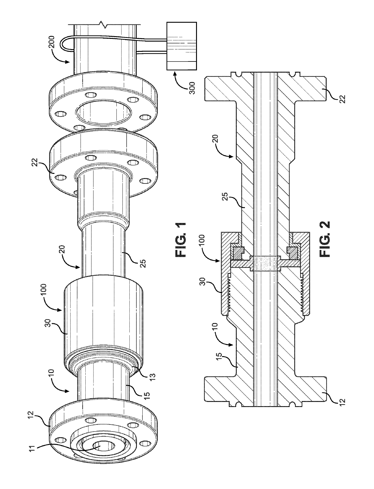
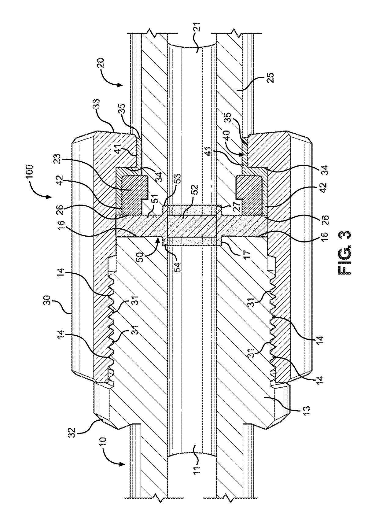
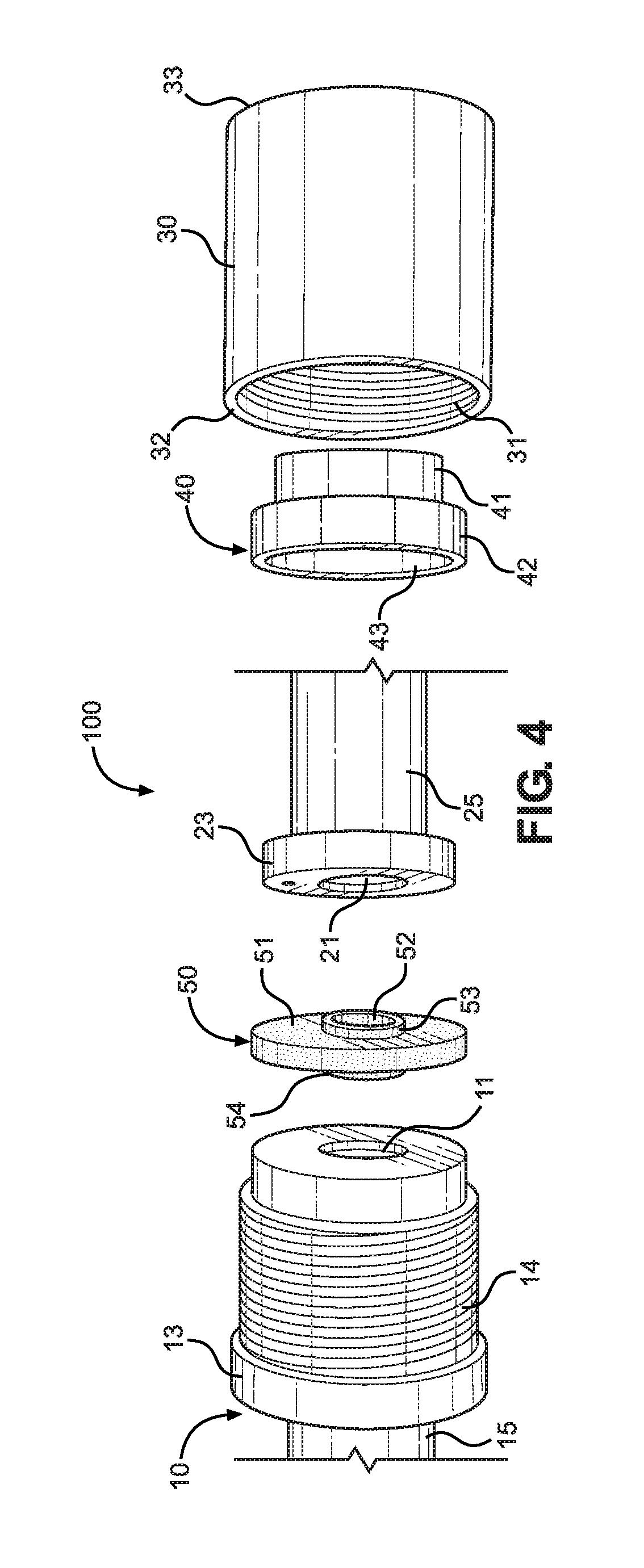
[0017]Referring to the drawings, FIG. 1 depicts a side perspective view of electrical conductivity interruption assembly 100 of the present invention. In a preferred embodiment, said electrical conductivity interruption assembly 100 of the present invention comprises a coupling or connection assembly that can be installed at one or more desired locations along the length of a tubular flow line or other pipeline. By way of illustration, but not limitation, said electrical conductivity interruption assembly 100 can be selectively installed within a length of flow line extending from an oil and / or gas well containing produced fluids (such as, for example, hydrocarbons and water produced from subterranean formations), as well as CO2, H2S and / or carbonic acid.

[0018]Further, by way of illustration, but not limitation, said electrical conductivity interruption assembly 100 can be installed within a flow line 200 that is being cathodically protected, including instances wherein electrical c...


PUM

PropertyMeasurementUnit
Electrical conductivityaaaaaaaaaa
Currentaaaaaaaaaa
Electrical conductoraaaaaaaaaa

Abstract

An isolating flow line spool fitting, particularly for electrical isolation of above-ground steel flow lines or other pipes. Two opposing half segments are electrically separated from each other by non-conductive isolating materials. A first half segment includes a threaded male connection member, while a second half segment includes a mating threaded collar for threadedly connecting the second half segment to the first half segment, and thereby forming a fluid pressure seal.

Description

FIELD OF THE INVENTION[0001]The present invention pertains to a cathodic protection or other protection system for fluid flow conduits and other piping systems. More particularly, the present invention pertains to protection of fluid flow conduits including, without limitation, flow lines in the oil and gas industry holding fluids containing CO2 / H2S media / carbonic acid. More particularly still, the present invention pertains to a method and apparatus for preventing corrosion from CO2 / H2S (Carbon Dioxide / Hydrogen Sulfide) in oil and gas production flow lines and / or other pipelines.BACKGROUND OF THE INVENTION[0002]It is well known that fluid flow through piping or tubular goods can cause damage to such piping / tubular goods by corrosion, erosion and / or other forces. This phenomenon is very common throughout many different applications, but it is particularly common in the oil and gas industry. In such applications, iron in steel pipes and / or other conduits (such as flow lines and the l...

Claims


Application Information

Patent Timeline
IPC IPC(8): F16L25/02
CPCF16L25/026F16L25/023Y10T29/49826F16L58/00C23F2213/11C23F2213/32C23F13/02
Inventor STEPHENS, BYRON P.SPIKES, ROBERT L.
Owner R & B INNOVATIONS LLC
Why Eureka
Try Eureka