
Weather tracking in a photovoltaic energy generation system

a photovoltaic energy and generation system technology, applied in the field of weather tracking in photovoltaic energy generation systems, can solve the problems of inability to accurately predict storms for downstream eg sites, and inability to accurately predict storms. the effect of weather conditions

Active Publication Date: 2019-07-23
TESLA INC
View PDF19 Cites 5 Cited by
  • Summary
  • Abstract
  • Description
  • Claims
  • Application Information

AI Technical Summary

Benefits of technology

The patent describes a method for controlling the load characteristics of a photovoltaic (PV)-based energy generation system based on the presence and density of cloud cover over the system. The method involves receiving power measurement data for the PV sites, calculating the difference between the present and historical power output, determining if cloud cover is present and calculating the density of cloud cover over the sites. The method can also include receiving weather forecast data, determining the vector path of the cloud cover, and controlling the load characteristics of the sites based on the presence and density of cloud cover. The technical effect of this method is to optimize the performance of the PV system by adjusting the load characteristics based on the cloud cover, which can lead to increased energy storage and better overall efficiency of the system.

Problems solved by technology

Despite these improvements, the power output for PV-based EG systems remain susceptible to bad weather conditions, including storm systems and dense cloud cover.
Bad weather conditions can greatly reduce an amount of sunlight that reaches PV-based EG systems, which can adversely affect their corresponding power generation.
However, conventional methods of storm forecasting for downstream EG sites are typically inaccurate, costly, and involve indirect calculations, broad assumptions, and imprecise estimations.

Method used


Image

  • Weather tracking in a photovoltaic energy generation system
  • Weather tracking in a photovoltaic energy generation system
  • Weather tracking in a photovoltaic energy generation system

Examples


an embodiment

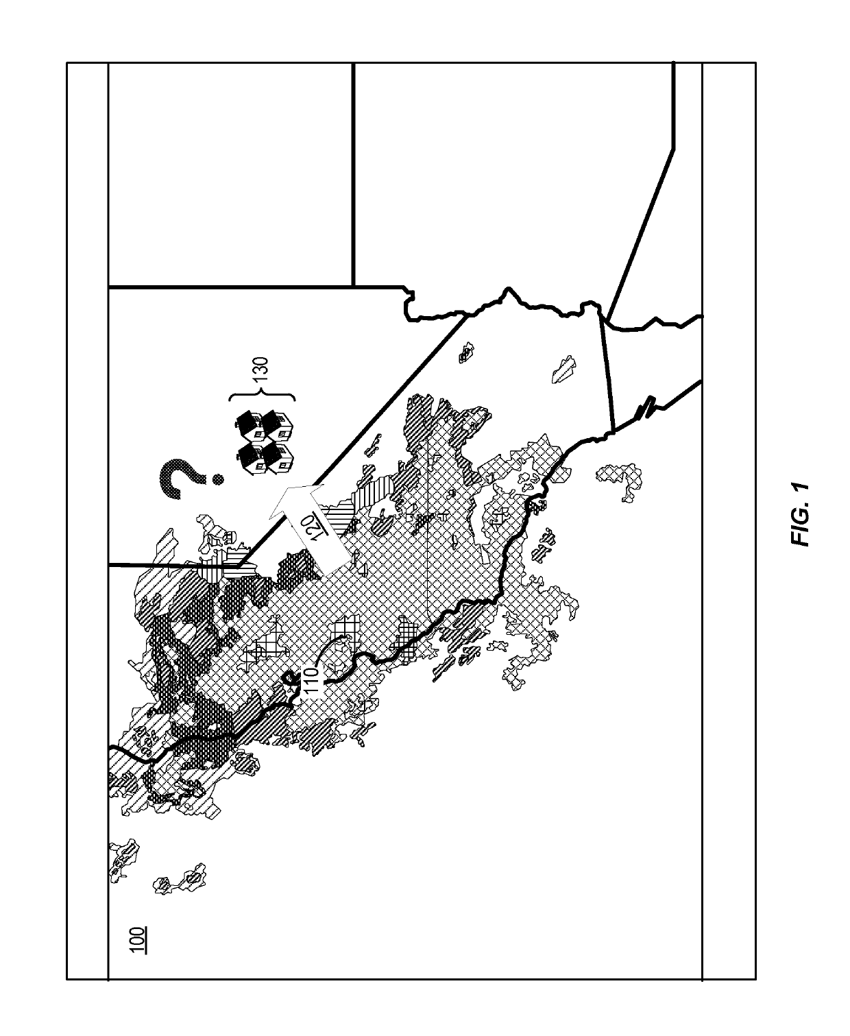
[0053]FIG. 4 shows aspects of a weather tracking system 400 using aspects of one or more PV-based EG sites, according to certain embodiments. Weather tracking system 400 can be used to track and characterize a weather pattern 410 over a number of PV-based EG sites 430 and forecast its effects on downstream EG sites 440. A number of PV-based EG sites are shown in locations across the State of California, U.S.A. Each EG site depicted can represent 1 EG site, 10 EG sites, 1000 EG sites, or any suitable representation. Weather patterns 410, 420 can include one or more clouds (i.e., cloud cover) that can block an amount of sunlight from reaching certain EG sites.

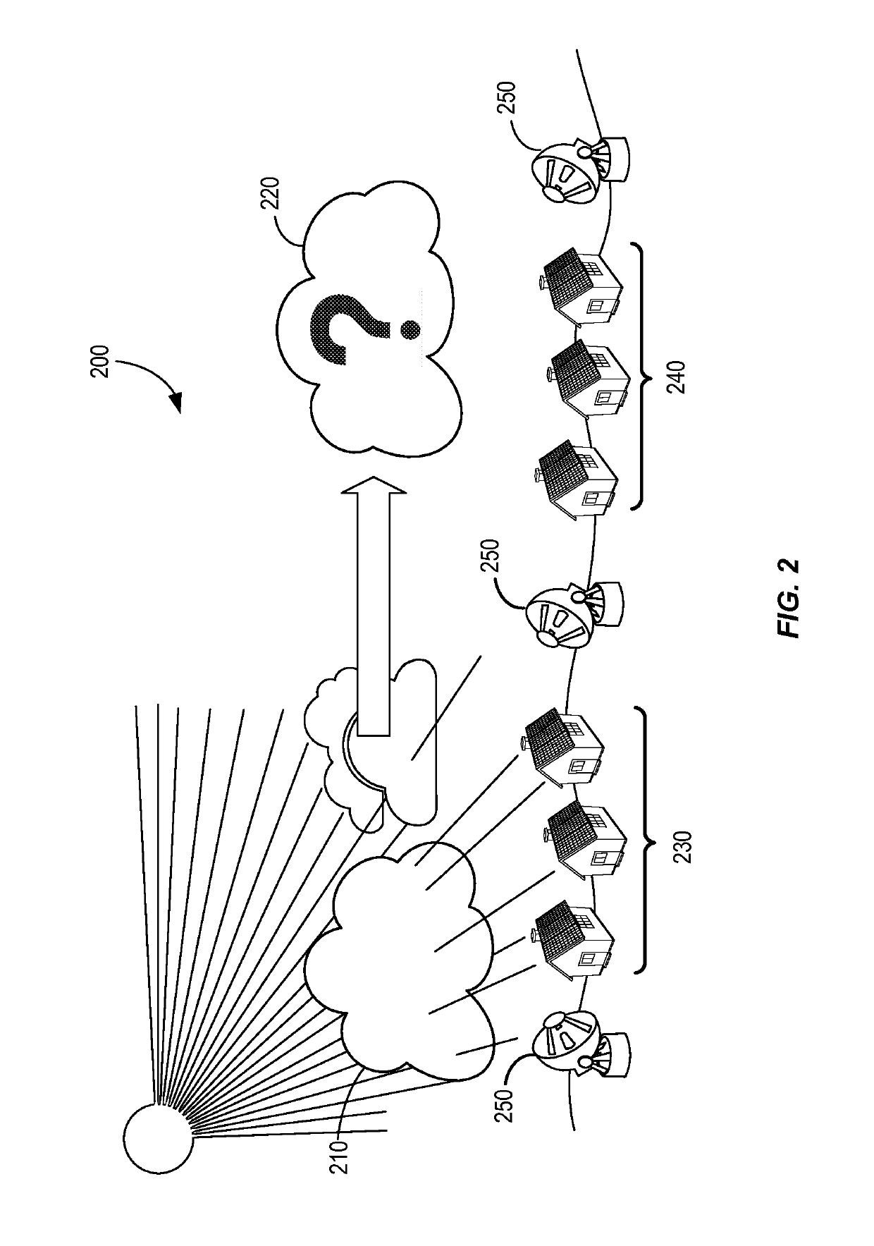
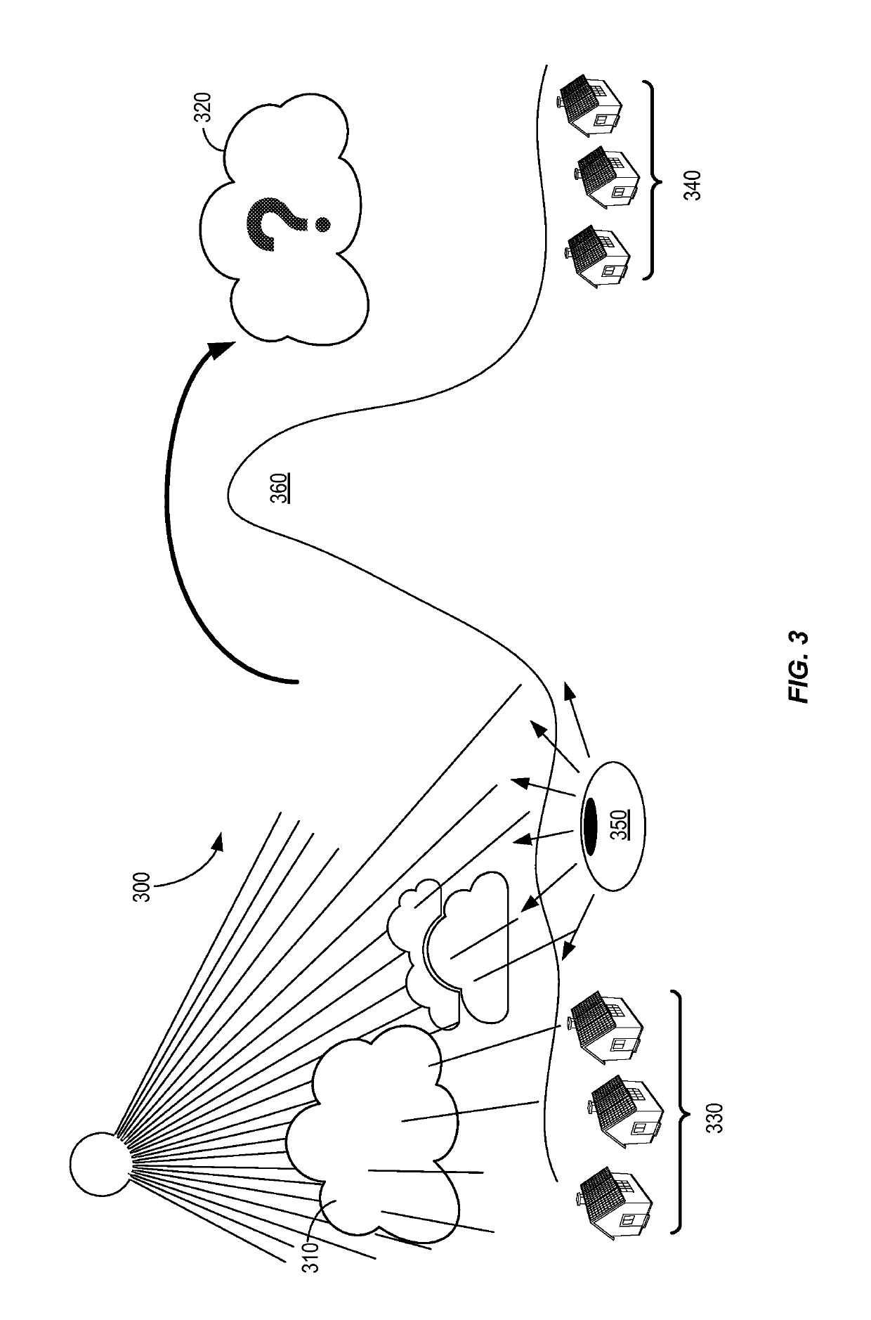
[0054]Weather tracking system (“system”) 400 has significant advantages over all conventional systems, including aspects of those shown in FIG. 1-3. System 400 utilizes the hardware and infrastructure in existing EG sites to perform the weather tracking operations. Thus, system 400 has virtually unlimited scalability with little ...


PUM


Abstract

A computer-implemented method includes receiving power measurement data for a photovoltaic (PV)-based energy generation (EG) sites, determining if cloud cover is present over the EG site based on a difference between a present and historical power output for the EG site, calculating a density of the cloud cover over the EG site based on the present and historical power outputs, and controlling load characteristics of the EG site based on the determined presence and calculated density of the cloud cover. The density of the cloud cover is based on a percentage difference in power output between the present power output and the historical power output. A vector for the cloud cover can be determined based on movement of a detected storm system with a boundary defined by a location of a plurality of EG sites, or by a movement of the cloud density from one EG site to the next.

Description

CROSS REFERENCE TO RELATED APPLICATIONS[0001]This claims the benefit of U.S. Provisional Application No. 62 / 155,444, filed Apr. 30, 2015, which is hereby incorporated by reference for all purposes.BACKGROUND[0002]In recent years, climate change concerns, federal / state initiatives, and other factors have driven a rapid rise in the installation of renewable energy generation (EG) systems (i.e., systems that generate energy using renewable resources such as solar, wind, hydropower, etc.) at residential and non-residential sites. Solar photovoltaic (PV) systems, in particular, have been very popular EG systems.[0003]PV-based EG systems have continued to improve as new innovations lead to lower manufacturing and installation costs, higher solar panel efficiencies, and greater control over energy distribution. Despite these improvements, the power output for PV-based EG systems remain susceptible to bad weather conditions, including storm systems and dense cloud cover. Bad weather conditi...

Claims


Application Information

Patent Timeline
Patent Type & Authority Patents(United States)
IPC IPC(8): G05F1/67G05B15/02H02J7/00H02J7/35H02M7/44
CPCG05F1/67G05B15/02H02J7/007H02J7/35H02M7/44H02J7/0052Y02E10/58Y04S10/123Y04S10/14H02J3/32H02J2203/20H02J2300/22H02J2300/24H02J3/381Y02E10/56Y02E40/70Y02E60/00Y04S40/20H02J13/00002Y04S10/30Y02E70/30H02J7/00
Inventor CARLSON, ERIC DANIEL
Owner TESLA INC
Learn More