Rotatable brim cap with stabilized track transition interface

a technology of transition interface and rotatable brim, which is applied in the field of caps and caps, can solve the problems of discontinuities in the track, interference with the relative movement of juxtaposed edges, and inability to prevent relative movements of juxtaposed edges, etc., and achieves the effect of easy and quick assembly, eliminating discontinuities, and quick and accurate alignmen

Active Publication Date: 2019-07-30
JUDGE CLAYTON
View PDF15 Cites 1 Cited by
  • Summary
  • Abstract
  • Description
  • Claims
  • Application Information

AI Technical Summary

Benefits of technology

[0007]It is still another object of the invention to provide a rotatable brim hat as in the previous objects that has a track that can be quickly and accurately aligned while eliminating discontinuities that would normally be experienced by a slide member attached to a brim. It is another object of the invention to provide a cap with a rotatable brim that is easily and quickly assembled.
[0008]It is still another object to provide a cap of the type under discussion that is simple in construction and economical to manufacture.
[0009]In order to achieve the above objects, as well as others that will become evident hereinafter, a cap with a rotatable brim in accordance with the invention comprises a cap with a rotatable brim, the cap having a crown with a substantially circular circumferential lower edge to fit on a wearer's head and has an inner surface along said lower edge. A brim has an arcuate edge attached to said crown and extends substantially outwardly away from said crown. An elongate track extends along said circumferential lower edge attached to said inner surface and has opposing free ends or edges when formed along a generally circular path. An elongate slide has a length substantially equal to said arcuate edge of said brim and is connected to said brim along said arcuate edge. Said track and slide form interlocking means for allowing movements of said elongate slide only along the entire length of said elongate track. First alignment means aligns the opposing edges when brought into abutment to form a substantially continuous track with an interface parting line. Second alignment means extends across at least a portion of said interface parting line to prevent relative movements of said opposing ends or edges about said first alignment means. Said first and second alignment means fix and stabilize said opposing edges at said interface parting line to maintain alignment and eliminate discontinuities of said opposing edges in said elongate track to insure smooth movements of said brim independently of the position of said brim along said elongate track.

Problems solved by technology

However, the free ends or edges, while in abutment, are not always in perfect alignment and this creates discontinuities that interfere with the free sliding movements of the brim when such discontinuities are encountered.
This may be frustrating when the brim is stopped during sliding movements and the track needs to be manipulated in order to allow the brim continued movement.
However, the use of such a double ended fastener or pin, while aligning the openings of the track, does not prevent relative movements of the juxtaposed edges relative to each other about the pin.
Since the edges can still move about the axis of the pin this introduces discontinuities in the track.
However, the bridge does not eliminate discontinuities of the track.

Method used


Image

  • Rotatable brim cap with stabilized track transition interface
  • Rotatable brim cap with stabilized track transition interface
  • Rotatable brim cap with stabilized track transition interface

Examples


Embodiment Construction

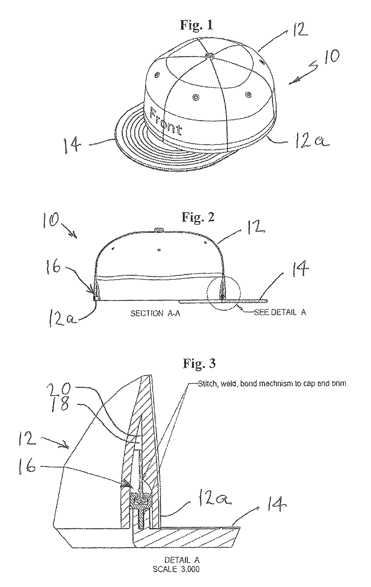
[0020]Referring now specifically to the Figures, in which identical or similar parts are designated by the same reference numerals throughout, and first referring to FIGS. 1 and 2, a cap in accordance with the invention is generally designated by the reference numeral 10.

[0021]The cap 10 includes a crown 12 having a lower circumferential edge 12a. The cap preferably includes a head band 12b to protect the wearer's head from contact with a guide or track assembly 16. The lower edge 12a and the headband 12b together form a circumferential or annular space 18 for housing the guide or track assembly 16 as best shown in FIG. 3. A brim or bill 14 has an arcuate edge attached to the crown 12 and extends substantially outwardly away from the crown as shown in FIGS. 1-3. The guide or track assembly 16 is secured within the space 18 in any conventional manner, such as stitching, adhesive, heat sealing or welding or the like to, for example, an inner surface 20 of the crown 12.

[0022]Referring ...


PUM


Abstract

A cap includes an elongate track that extends along the lower edge of the crown has opposing free ends or edges when formed along a generally circular path. A slide, connected to the brim, can slide along the track. A pin or wire aligns the opposing edges of the track when brought into abutment to form an interface parting line. One or more tapes extend across the interface parting line to prevent relative movements of the opposing edges about the pin or wire thereby fixing and stabilizing the opposing edges at the interface parting line to maintain alignment and eliminate discontinuities at the opposing edges to insure smooth movements of the brim independently of the position of said brim along the track.

Description

BACKGROUND OF THE INVENTION1. Field of the Invention[0001]The present invention generally relates to hats and caps and, more specifically, to a cap with a rotatable brim having a stabilized track transition interface to ensure simple and seamless movements of the brim about circumference of the crown of the cap.2. Description of the Prior Art[0002]Numerous hats and caps with moveable brims have been proposed. Examples of such hats are disclosed in the following patents: U.S. Pat. Nos. 5,715,534, 5,870,772, 66,263,508, U.S. Publication No. US 2004 / 0040067 and U.S. Pat. No. RE38,774.[0003]All of the caps disclosed in the aforementioned patents utilize track or guide assemblies for sliding the brim in relation to the cap crown. The guide assemblies typically include an elongate track with free ends or edges, the track being formed into a generally circular configuration to bring the free edges into juxtaposed positions or into abutment with each other. The slide attached to the brim ca...

Claims


Application Information

Patent Timeline
Patent Type & Authority Patents(United States)
IPC IPC(8): A42B1/06A42B3/04
CPCA42B1/064A42B1/0184
Inventor JUDGE, CLAYTON
Owner JUDGE CLAYTON
Why Eureka
Try Eureka