Wireless electrical system and method for indicating working area of ​​wireless electrical system

A technology for wireless appliances and working areas, applied in current collectors, battery circuit devices, electric vehicles, etc., can solve the problems of low wireless energy transmission efficiency, achieve high energy transmission efficiency, and save energy

Active Publication Date: 2019-07-16
深圳前海贞泰通信技术有限公司
View PDF4 Cites 0 Cited by
  • Summary
  • Abstract
  • Description
  • Claims
  • Application Information

AI Technical Summary

Problems solved by technology

[0007] Aiming at the technical problem of low wireless power transmission efficiency caused by the difficulty in alignment of the transmitting coil and the receiving coil in the above-mentioned wireless power supply electrical appliance system, the present invention proposes a wireless power supply system that can place electrical appliances to be powered according to the indicated position, and provides a wireless power supply system using the Indication method of working area for wireless power supply by wireless power supply system

Method used


Image

  • Wireless electrical system and method for indicating working area of ​​wireless electrical system
  • Wireless electrical system and method for indicating working area of ​​wireless electrical system
  • Wireless electrical system and method for indicating working area of ​​wireless electrical system

Examples


Embodiment Construction

[0032] In the following, the present invention will be specifically described through exemplary embodiments. It should be understood, however, that elements, structures and characteristics of one embodiment may be beneficially incorporated in other embodiments without further recitation.

[0033] In the description of the present invention, it should be noted that the terms "first" and "second" are only used to describe the difference in power required by different working modes, and should not be understood as indicating or implying importance.

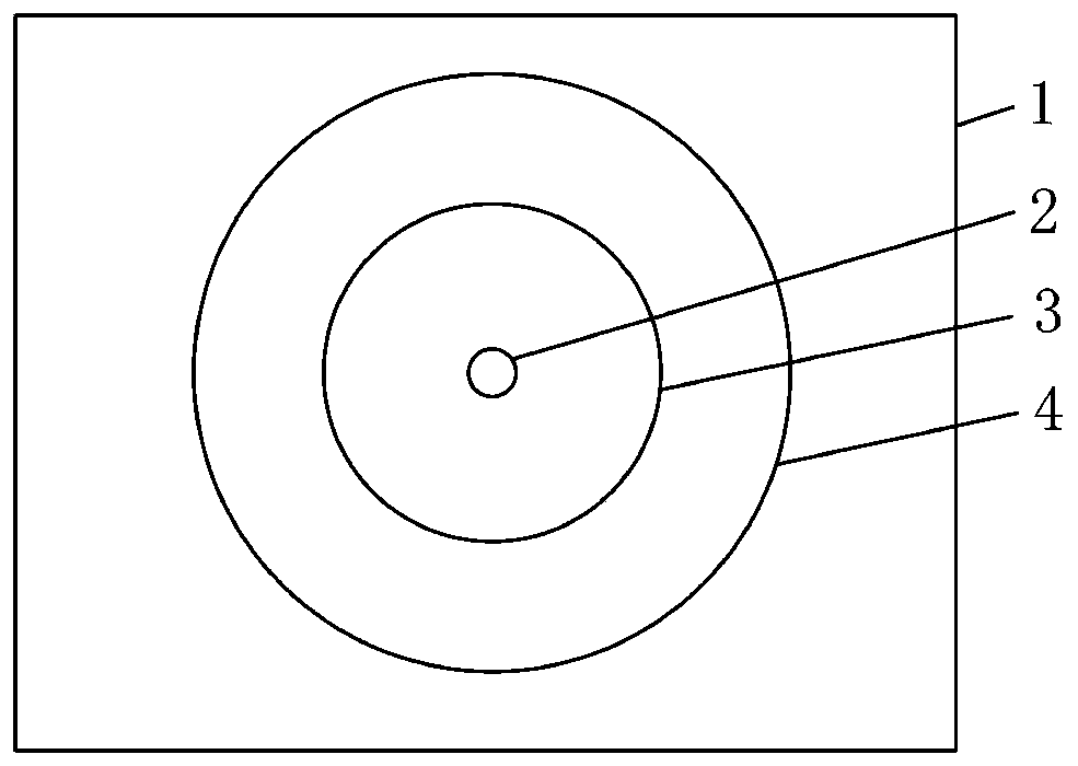
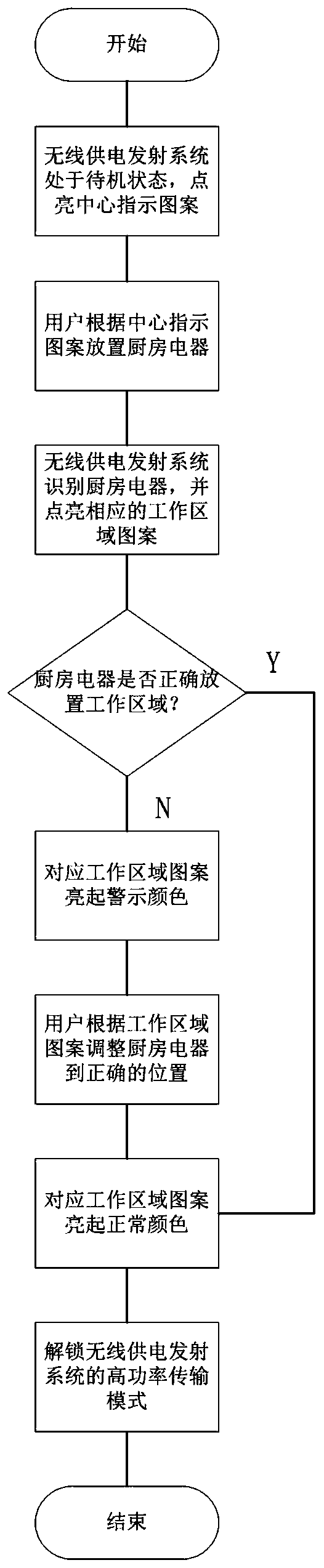
[0034] The wireless electrical system includes the main electrical appliance and the wireless power supply transmitting system, the main electrical appliance includes the receiving coil, the wireless power supply transmitting system includes the transmitting coil, the transmitting end control processing module and the data sensing unit for collecting the wireless power supply working parameters of the main electrical appliance, wirele...


PUM


Abstract

The invention provides a wireless electric appliance system comprising a main body electric appliance and a wireless power supply transmitting system, wherein a power supply area indicating symbol with a variable indicating state and used for indicating a wireless power supply area is arranged on a power supply table top of the wireless power supply transmitting system, and the state of the power supply area indicating symbol is controlled according to a comparison result of a power supply working parameter and a power supply parameter threshold obtained by a transmitting terminal control processing module in a wireless power supply process so as to indicate a user to adjust the position of the main body electric appliance to align a transmitting coil with the a receiving coil, in order to realize efficient wireless power supply.

Description

technical field [0001] The invention belongs to the field of wireless appliances, and relates to a wireless appliance system and a method for indicating a working area of ​​the wireless appliance system. Background technique [0002] With the improvement of living standards and the development of science and technology, people have applied wireless power supply technology to many fields of life. Different from the traditional wired power supply, the electrical appliance end and the wireless power supply end of the wireless power supply system use wireless transmission to transmit electric energy and communication signals. [0003] Take the application of wireless power supply technology in the technical field of kitchen appliances as an example, such as the electrical power supply device disclosed in ZL201220338889.0, and also discloses a tailless kitchen appliance. The electrical power supply device converts electrical energy into electromagnetic energy, and uses the princ...

Claims


Application Information

Patent Timeline
Patent Type & Authority Patents(China)
IPC IPC(8): H02J50/10H02J50/90H02J7/02
CPCH02J7/025H02J50/10H02J50/90
Inventor 娄兵兵刘超李标孙会刁德鹏
Owner 深圳前海贞泰通信技术有限公司
Why Eureka
Try Eureka