
Apparatus for detecting relative positioning information between rolls, and method for measurement roll alignment state by using same

a technology of relative positioning information and detecting apparatus, which is applied in the direction of measuring devices, instruments, and using reradiation, can solve the problems of lowering productivity such as production suspension, and the effectiveness of patent literature 1, and achieve the effects of easy measurement and inspection, accurate measurement and output, and convenient measurement and inspection

Active Publication Date: 2021-12-07
PCM SOLUTION CO LTD +2
View PDF9 Cites 0 Cited by
  • Summary
  • Abstract
  • Description
  • Claims
  • Application Information

AI Technical Summary

Benefits of technology

Enables easy and accurate measurement and correction of roll alignment, improving the efficiency and reliability of roll process lines by providing intuitive alignment data and reducing the need for high-resolution sensors, thus enhancing product quality and reducing defects.

Problems solved by technology

Also, this eventually causes wrinkles, waveforms, overlapping, and thickness deviation of the product, and causes the film to break during operation, resulting in a problem of lowering productivity such as production suspension.
In consideration of this, Patent Literature 1 and Patent Literature 2 are limited in being effectively used in the field unless a sensor having a high resolution is installed.
Therefore, measuring the alignment of the measuring the rolls at a certain distance from the subject roll takes a long time because it is difficult to adjust the position so that the laser signal can be irradiated to the exact center point of the first reflector.
In particular, this raises a problem in terms of ease of measurement that makes handling difficult except for skilled workers.
However, when applied in the field, another problem occurred only in the Patent Literature 2.
Therefore, there is another problem in that it is difficult to immediately check measurement information on whether the measurement roll is inclined in the direction of the subject roll or in a direction away from the subject roll, only with the output coordinates (if the irradiation location, at which the laser of the subject roll is irradiated to the laser receiving unit constituted in the measurement roll, is the same, it cannot be determined whether the measurement roll is inclined in a direction away from the subject roll or close to the subject roll).
In addition, there is still a problem that the accuracy of the measurement result is increased only when a sensor having an advanced resolution is installed.
That is, when the parallelism of the measurement roll with respect to the subject roll is measured in Patent Literature 2, there is a problem in that the measurer does not immediately recognize whether it measurement roll is inclined in a direction closer to the subject roll or inclined in a direction away from the subject roll based on only the coordinate values of the output parallelism.
In addition, there is another problem in that an expensive measuring device is inevitably provided due to high-resolution sensors.
In this case, there is a problem that cannot be solved simply because it is necessary to establish an organic coupling relationship with the existing components.
Also, a limitation of the measurement range due to the difference in the resolution of the sensor cannot be easily solved.

Method used


Image

  • Apparatus for detecting relative positioning information between rolls, and method for measurement roll alignment state by using same
  • Apparatus for detecting relative positioning information between rolls, and method for measurement roll alignment state by using same
  • Apparatus for detecting relative positioning information between rolls, and method for measurement roll alignment state by using same

Examples


Embodiment Construction

[0136]Hereafter, the functions, configuration, and operations of an apparatus for detecting relative positioning information between rolls and a method for measuring roll alignment state using the apparatus of the present disclosure are described with reference to the accompanying drawings.

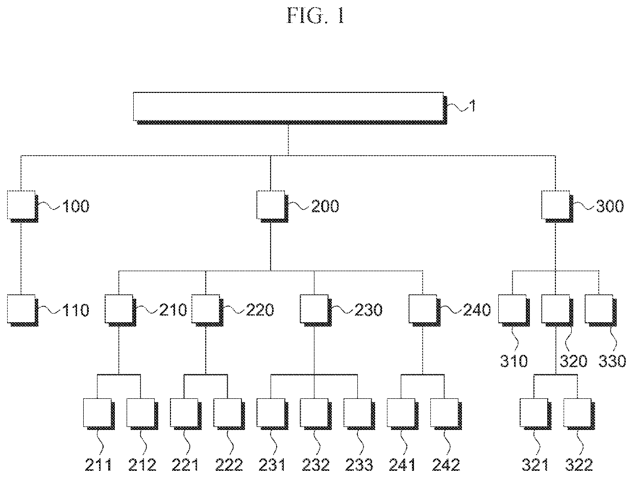
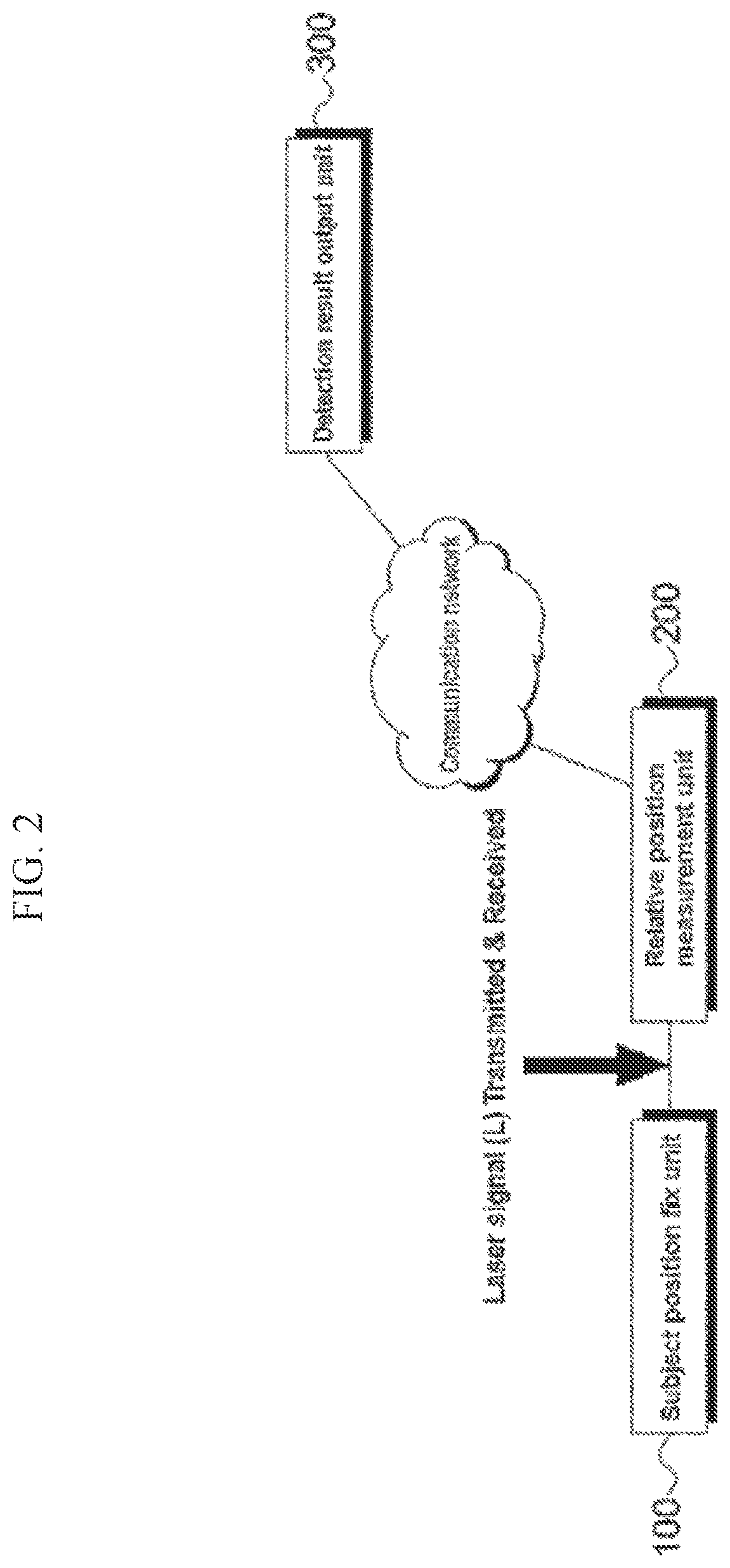
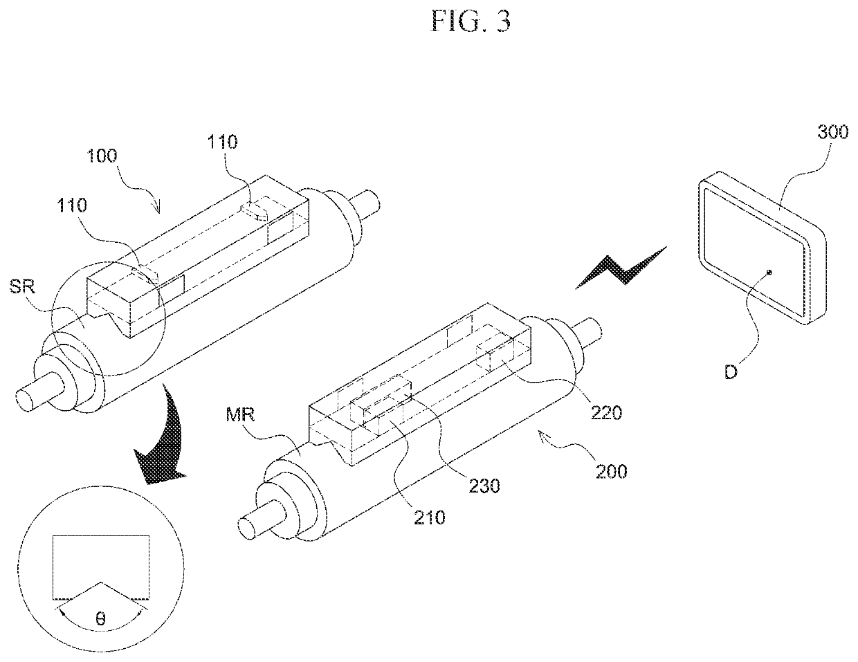
[0137]FIG. 1 is a diagram showing the configuration of an apparatus for detecting relative positioning information between rolls of the present disclosure, FIG. 2 is a diagram showing the concept of the apparatus for detecting relative positioning information between rolls of the present disclosure, FIG. 3 is a perspective view of the apparatus for detecting relative positioning information between rolls of the present disclosure, FIG. 4 is a view showing an example where the apparatus for detecting relative positioning information between rolls of the present disclosure is applied to a site, and FIG. 5 is a plan view showing an example of measurement by the apparatus for detecting relative positi...


PUM

PropertyMeasurementUnit
lengthaaaaaaaaaa
lengthaaaaaaaaaa
contained angleaaaaaaaaaa

Abstract

The present invention relates to an apparatus for detecting relative positioning information between rolls, and a method for measuring a roll alignment state by using same, and to an apparatus for detecting relative positioning information between rolls, and a method for measuring a roll alignment state by using same, the apparatus outputting a measurement result in real time so that a measurer can easily recognize the degree of parallelism and the degree of horizontality of a roll when a roll process line is formed, and thus an inter-roll alignment state can be checked or a measurement roll can be corrected according to the alignment state.

Description

TECHNICAL FIELD[0001]The present invention relates to an apparatus for detecting relative positioning information between rolls and a method for measurement roll alignment state by using the apparatus. In more detail, the present invention relates to an apparatus for detecting relative posture positioning information between rolls in which the apparatus outputs a measurement result in real time so that a measurer can easily recognize the alignment state of a roll, that is, the degree of parallelism and the degree of horizontality of a measurement roll to be measured with respect to a subject roll when constructing a roll process line including sequential rolls such that the alignment state between rolls can be checked and the measurement roll can be corrected in accordance with the alignment, wherein a laser signal, which is discharged from a subject position fix unit mounted on the subject roll, is reflected in a relative position measurement unit mounted on the measurement roll so...

Claims


Application Information

Patent Timeline
Patent Type & Authority Patents(United States)
IPC IPC(8): B21B38/00G01B11/27
CPCB21B38/00G01B11/272G01B11/26G01C9/00G01S17/88G01S17/08B21B38/12B21B2203/18
Inventor JEONG, HONG SEOK
Owner PCM SOLUTION CO LTD
Learn More