Slide rail assembly and rack system

a technology of sliding rails and racks, applied in the direction of support structure mounting, domestic applications, servers, etc., can solve the problems that the sliding rail cannot be extended beyond the rear end of the rack as well as in the forward direction of the rack

Active Publication Date: 2019-08-13
KING SLIDE WORKS CO LTD +1
View PDF14 Cites 4 Cited by
  • Summary
  • Abstract
  • Description
  • Claims
  • Application Information

AI Technical Summary

Benefits of technology

[0005]Preferably, the slide rail assembly further includes a third rail movably connected to the second rail to increase the extension length of the slide rail assembly.
[0008]Preferably, the slide rail assembly further includes a simultaneous displacement mechanism. The simultaneous displacement mechanism includes a first elastic element, a first moving element, and an engaging element. The first moving element is arranged on the second rail and is at an initial position in response to the first elastic element generating an elastic force. The engaging element is arranged on the third rail and corresponds to a portion of the first moving element. When the third rail is displaced from the retracted position with respect to the first rail in the first direction, the first moving element on the second rail and the engaging element on the third rail abut against each other so that the second rail and the third rail can be displaced simultaneously.

Problems solved by technology

This slide rail, however, cannot be extended beyond the rear end of a rack as well as in a forward direction of the rack once mounted at a fixed position on the rack.

Method used


Image

  • Slide rail assembly and rack system
  • Slide rail assembly and rack system
  • Slide rail assembly and rack system

Examples


Embodiment Construction

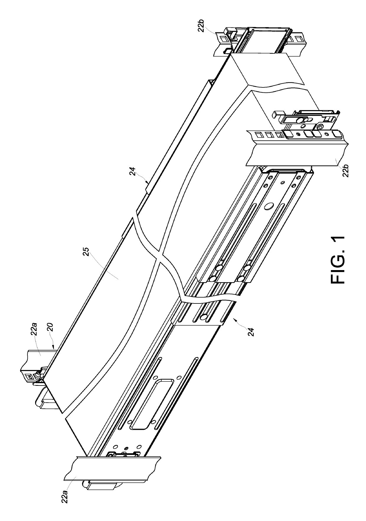
[0038]Referring to FIG. 1, the rack system according to one embodiment of the present invention includes a rack 20. The rack 20 includes a pair of front posts 22a and a pair of rear posts 22b. A pair of slide rail assemblies 24 are each mounted between the corresponding front post 22a and the corresponding rear post 22b of the rack 20 and are configured to carry an object 25, such as a piece of electronic equipment.

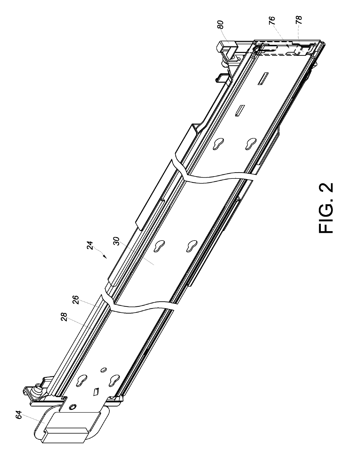
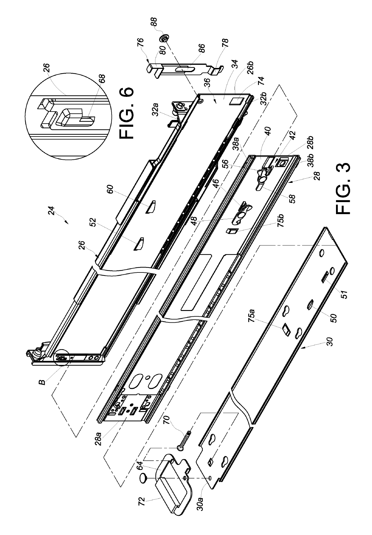
[0039]Referring to FIG. 2 and FIG. 3, the slide rail assembly 24 includes a first rail 26, a second rail 28, and a third rail 30. The first rail 26 includes an upper wall 32a, a lower wall 32b, and a sidewall 34 extending between the upper wall 32a and the lower wall 32b. The upper wall 32a, the lower wall 32b, and the sidewall 34 jointly define a first channel 36 for receiving the second rail 28.

[0040]Similarly, the second rail 28 includes an upper wall 38a, a lower wall 38b, and a sidewall 40 extending between the upper wall 38a and the lower wall 38b. The upper wall 38...


PUM


Abstract

A slide rail assembly includes a first rail, a second rail, and a blocking member. The blocking member is arranged adjacent to the rear end of the first rail and can be operated so as to enter or exit a blocking state. The blocking member in the blocking state serves to block the rear end of the second rail. When the blocking member is not in the blocking state, and the second rail reaches a rearwardly extended position after displacement with respect to the first rail, the rear end of the second rail extends beyond the rear end of the first rail.

Description

FIELD OF THE INVENTION[0001]The present invention relates to a slide rail assembly and more particularly to one adjustable for displacement in two directions.BACKGROUND OF THE INVENTION[0002]Evans et al. disclose a bidirectional slide rail in US Patent Application Publication No. 2014 / 0265793 A1. This slide rail, however, cannot be extended beyond the rear end of a rack as well as in a forward direction of the rack once mounted at a fixed position on the rack. In practical use, therefore, the slide rail still leaves room for improvement.SUMMARY OF THE INVENTION[0003]The present invention relates to a slide rail assembly that can be adjusted for bidirectional displacement.[0004]According to one aspect of the present invention, a slide rail assembly includes a first rail, a second rail, and a blocking member. When the second rail reaches a forwardly extended position after being displaced with respect to the first rail in a first direction, the front end of the second rail extends bey...

Claims


Application Information

Patent Timeline
Patent Type & Authority Patents(United States)
IPC IPC(8): A47B88/403H05K7/14
CPCA47B88/403H05K7/1489A47B2210/0081A47B2210/0018A47B88/50
Inventor CHEN, KEN-CHINGYANG, SHUN-HOYEH, CHIH-HSINWANG, CHUN-CHIANG
Owner KING SLIDE WORKS CO LTD
Why Eureka
Try Eureka