Adjusting mechanism for brake handle

A brake handle and adjustment mechanism technology, which is applied in the mechanical field, can solve the problems of small adjustment distance of the handle, jamming, etc., and achieve the effects of stable rotation, reduced damage, and wide application range

Inactive Publication Date: 2008-09-10
YUHUAN KAILING MASCH GRP CO LTD
View PDF1 Cites 2 Cited by
  • Summary
  • Abstract
  • Description
  • Claims
  • Application Information

AI Technical Summary

Problems solved by technology

In this patent, the adjustment between the front of the handle and the rear of the handle is realized through the center sleeve. Since the center sleeve is installed between the front of the handle and the rear of the handle, the adjustment distance of the handle is small, which cannot meet the wishes of most people.
In addition, since the rear part of the handle is to swing and rotate, while the center sleeve is stretched and shortened in a straight line, if the adjustment distance between the rear part of the handle and the front part of the handle is too large, it will be stuck

Method used


Image

  • Adjusting mechanism for brake handle
  • Adjusting mechanism for brake handle

Examples


Embodiment 2

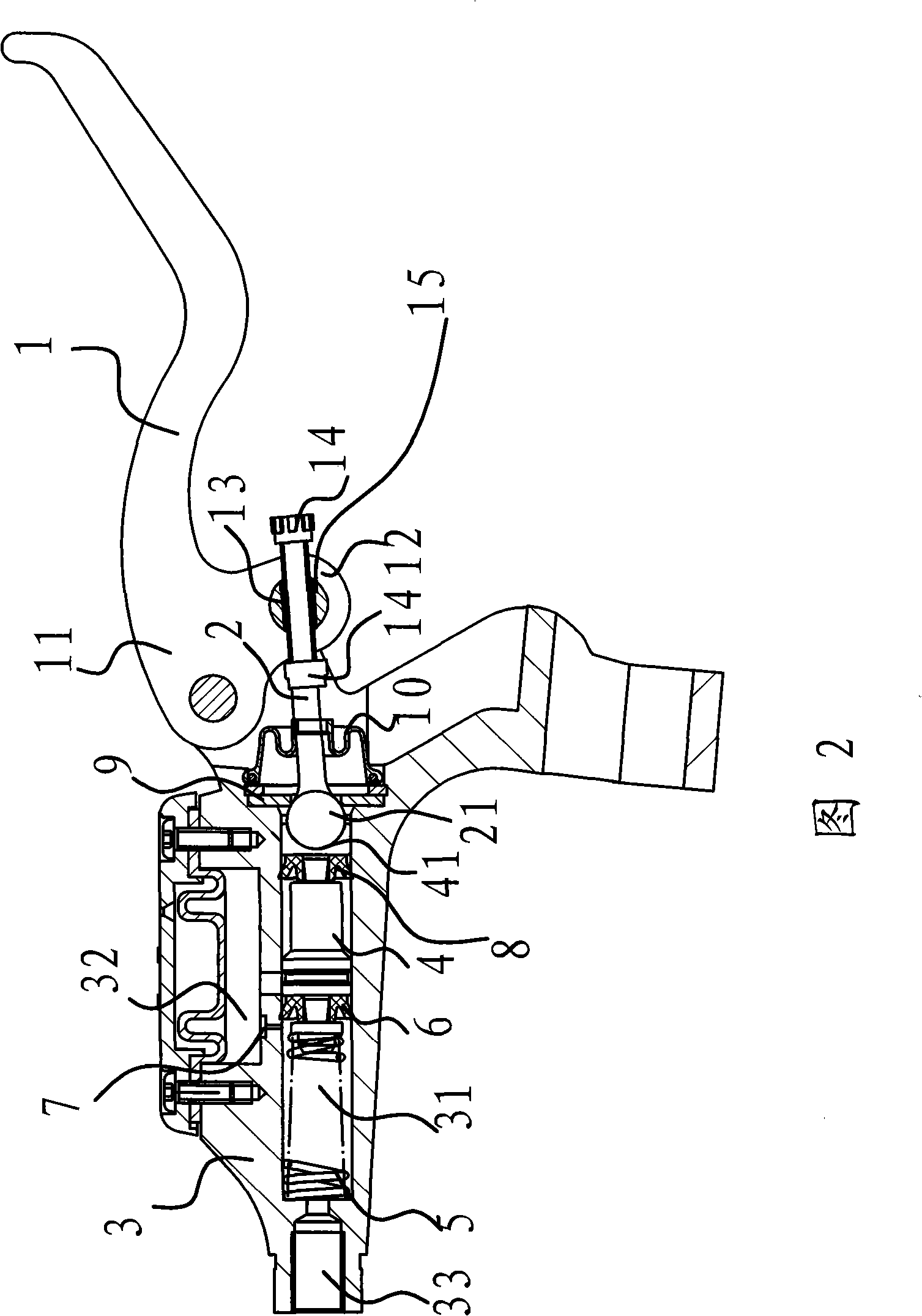
[0033] As shown in Figure 2, the content of embodiment 2 is basically the same as that of embodiment 1, the difference is that the positioning structure includes a guide hole 13 on the connecting part 12, the outer end of the connecting rod 2 passes through the guide hole 13, And can axially slide in guide hole 13, be provided with two adjustment nuts 14 on the outer end of connecting rod 2, these two adjustment nuts 14 are respectively positioned at the both sides of guide hole 13, and two adjustment nuts 14 and connecting rod 2 are connected by threads. After the outer end of the connecting rod 2 passes through the guide hole 13, its adjusting nut 14 is located on both sides of the connecting portion 12 of the brake handle 1, and the position of the brake handle 1 can be adjusted by turning the adjusting nut 14 respectively. Since the connecting rod 2 slides through the handle, when the brake handle 1 rotates, the outer end of the connecting rod 2 also slides outwards accord...

Embodiment 3

[0035] The content of embodiment 3 is basically the same as that of embodiment 1, except that the positioning structure includes an adjusting nut 13 and a worm wheel arranged on the brake handle 1, and the worm wheel is fixed on the brake handle 1 in a circumferentially rotatable manner. The above-mentioned connecting rod 2 passes through the adjusting nut 14 and can slide axially in the adjusting nut 14. The connecting rod 2 in the adjusting nut 14 is in the shape of a worm and meshes with the worm wheel. There is a spring that makes the brake handle 1 lean against the positioning structure.

[0036] When the worm wheel is turned, the connecting rod 2 moves axially in the guide hole 13 under the action of the worm wheel. When the worm wheel rotates in the forward direction, the worm wheel drives the brake handle 1 to rotate in a direction close to the pump body 3 , and vice versa, the worm wheel drives the brake handle 1 to rotate in a direction away from the pump body 3 . B...


PUM


Abstract

The invention provides a regulating mechanism for brake handle, which belongs to the technical field of the machinery. The regulating mechanism solves the problem that the phenomenon of deadlocking occurs if the regulative distance between the rear part and front part of the handle of the regulating mechanism of the prior brake handle is too large. The regulating mechanism of the brake handle is arranged between a hydraulic brake pump and a brake handle and the hydraulic brake pump comprises a pump body and a piston arranged inside the pump body; the brake handle is hinged with the pump body and a connecting rod is arranged between the piston and the brake handle; one end of the connecting rod is connected with the external end of the piston in a rotary way and the other end of the connecting rod passes through the brake handle and can relatively move with the brake handle; a positioning structure which can regulate the position of the brake handle is arranged between the connecting rod and the brake handle. The regulating mechanism of the brake handle has simple structure, big regulative distance of the brake handle and has no effect on the idle stroke of the piston.

Description

technical field [0001] The invention belongs to the technical field of machinery and relates to a brake handle, in particular to an adjustment mechanism for a brake handle of motorcycles, bicycles or other non-motor vehicles. Background technique [0002] At present, the opening degree between the brake handle and the clutch handle used on motor vehicles or bicycles is not adjustable. Due to the different sizes of hands, no matter what kind of opening is designed as the opening between the brake handle and the clutch handle, it cannot be suitable for all users; When the handle is moved, it will be out of reach and cannot be braked in time; if the user's hand is large, but the opening is too small, the brake will actually be braked while the user feels that the brake has not been completed, and it will also cause safety accidents. In addition, it affects the braking comfort. For this reason, the opening between the brake handle and the clutch handle needs to be frequently ...

Claims


Application Information

Patent Timeline
Patent Type & Authority Applications(China)
IPC IPC(8): B62K23/02
CPCB62L3/023
Inventor 赵跃
Owner YUHUAN KAILING MASCH GRP CO LTD
Why Eureka
Try Eureka