
Speech valve for persons having undergone a laryngectomy or tracheotomy

a technology for speech valves and laryngectomyes, which is applied in the direction of tracheae, tubular organ implants, larynxes, etc., can solve the problems of increased mucous production, clogging, and fatigue of filter materials,

Active Publication Date: 2019-08-27
ANDREAS FAHL MEDIZINTECHNIK VERTRIEB GMBH
View PDF9 Cites 0 Cited by
  • Summary
  • Abstract
  • Description
  • Claims
  • Application Information

AI Technical Summary

Benefits of technology

The present invention aims to provide a durable speech valve that requires minimal force to transition between open and closed positions while still retaining functionality. The speech valve has a cover with a retaining means for the valve element, which ensures secure closing and prevents impairment of the filter's moisture exchange function. The valve element is designed to provide feedback to the user during the transition to the closure position.

Problems solved by technology

This is because mucous production increases with the irritation caused thereby, accompanied by the danger of clogging as a consequence.
The disadvantage with this, in particular, is that on one hand, the filter material becomes fatigued through the compression and decompression during the transitions into the closure position and the open position of the voice valve, and on the other hand, the elastic property of the filter material weakens through use, such that a secure opening and closing is no longer obtained.

Method used


Image

  • Speech valve for persons having undergone a laryngectomy or tracheotomy
  • Speech valve for persons having undergone a laryngectomy or tracheotomy
  • Speech valve for persons having undergone a laryngectomy or tracheotomy

Examples


first embodiment

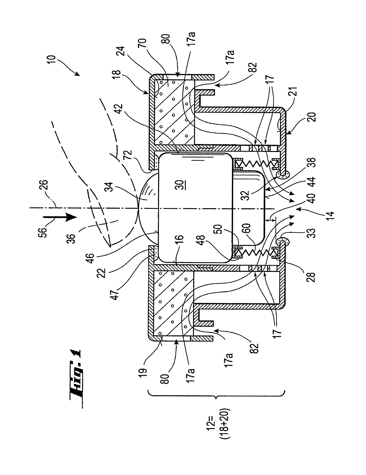
[0031]FIG. 1 shows, in an enlarged view, the speech valve 10 according to the invention, having a housing 12, in the open position. The housing 12 has a proximal opening 14 in the vicinity of the body. The speech valve 10 is stuck onto a tracheal cannula or an adhesive bandage, not shown here, which is glued over the stoma of the wearer, by way of example. Typical connectors, in the DIN-norm as well, e.g. with a 15 mm or 20 mm diameter, are known for this.

[0032]The housing 12 has openings 80 oriented such that they are perpendicular in relation to a central main axis 26, and openings 82 that are oriented parallel thereto, through which air 17a can flow through a filter 70 in the interior of the housing 12 and into the stoma of a user via the proximal first opening 14, when the speech valve 10 is in the open position, and also flow out in the opposite direction via the proximal first opening 14, through the openings 80 and 82, after passing through the filter 70. The openings 80 and ...

third embodiment

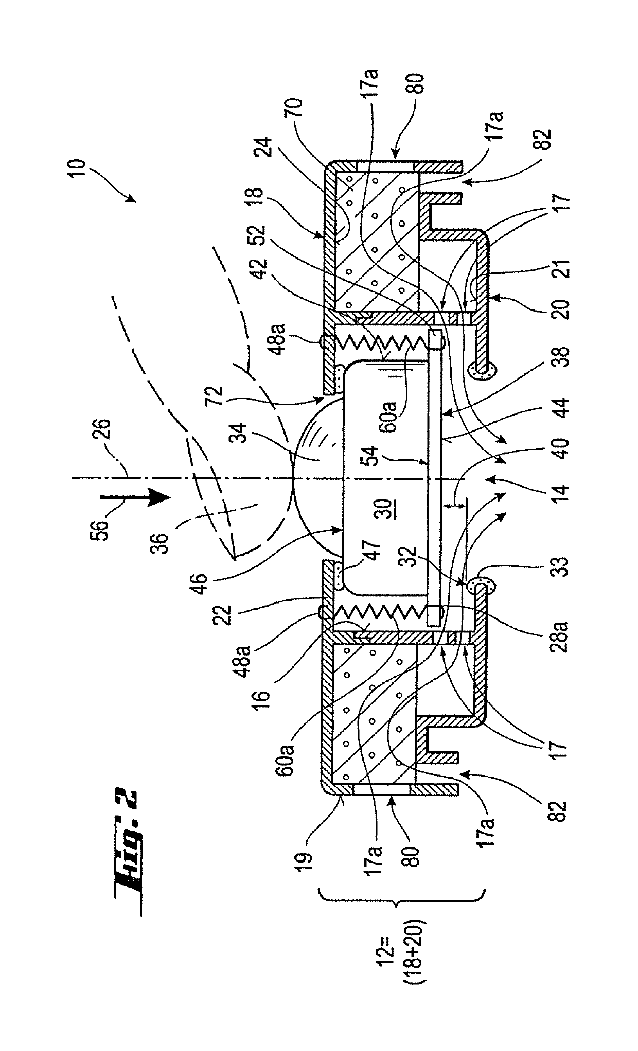
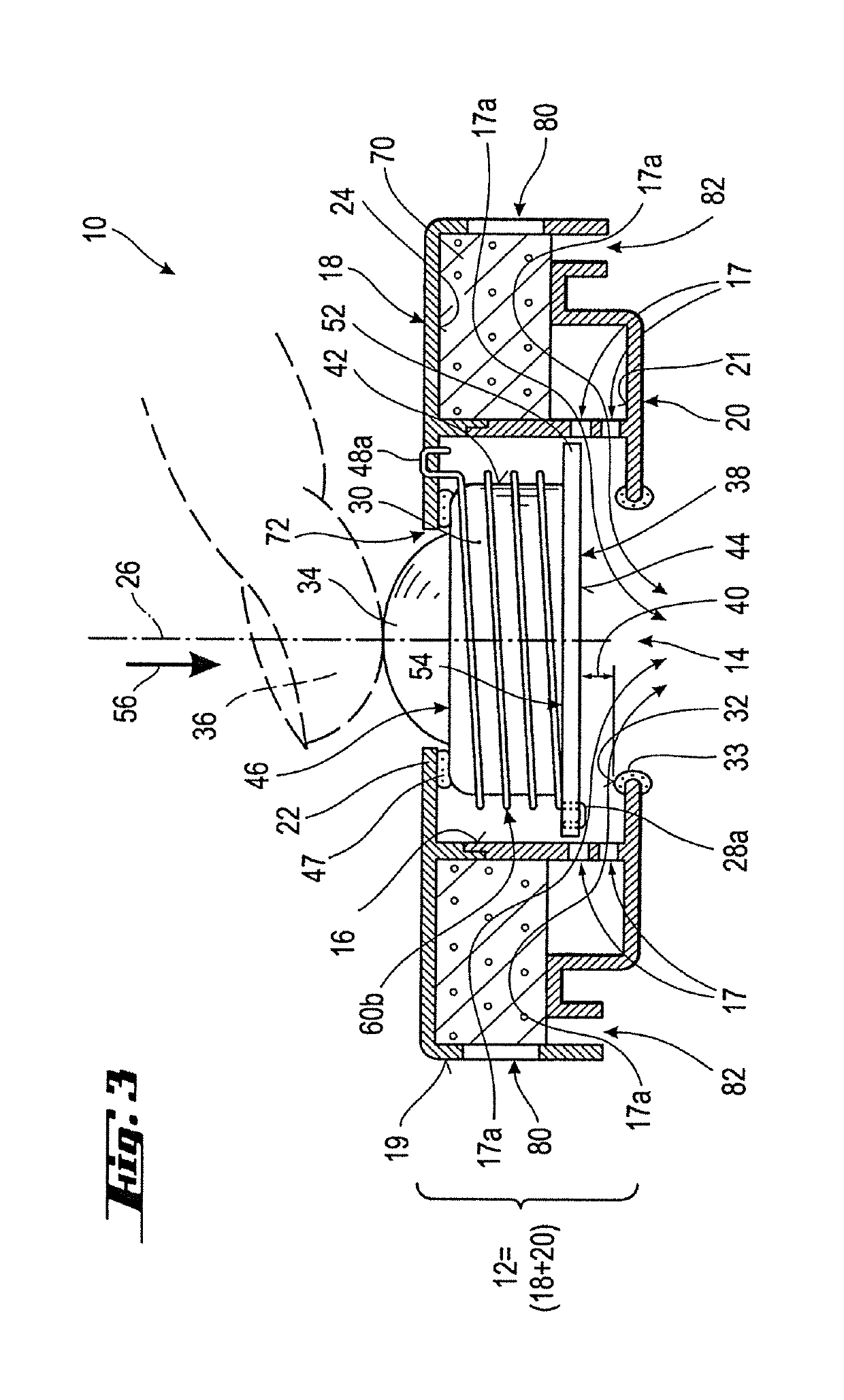
[0041]FIG. 3 shows an alternative third embodiment of the speech valve 10 according to the invention. In differing from the embodiment shown in FIG. 2, only one helical spring 60b is provided, in which the valve element 30 is partially received, wherein the undersurface 24 of the cover part 18 serves as an attachment point 28b for the helical spring 60b. The other attachment point 28b for the helical spring 60b is formed by the widening 52 of the valve element 39, corresponding to the embodiment shown in FIG. 2.


PUM


Abstract

To solve the problem of making available a speech valve for persons who have undergone a laryngectomy or tracheotomy, which speech valve in particular has a long useful life, a speech valve (10) is proposed having a housing (12) with a proximal opening (14) and at least one filter (70) at least partially received in the housing, and with a piston-like valve element (30), wherein the filter at least partially surrounds the valve element, wherein the valve element is movable on a valve seat (32), arranged on the proximal opening, in order to produce a closure position and can be returned with a spring action to an open position of the speech valve, and wherein the valve element has a lower end (38) which faces towards the proximal opening and which is assigned to the valve seat in the open position and, with the valve seat, forms a gap (40) through which an air stream (17a) can be guided.

Description

CROSS-REFERENCE TO RELATED APPLICATIONS[0001]This application is a continuation of PCT Patent Application PCT / EP2014 / 002934 filed on Nov. 3, 2014, which claims priority of German Patent Application 10 2013 018 423.1 filed on Nov. 4, 2013.FIELD OF THE INVENTION[0002]The present invention relates to a speech valve for persons having undergone a laryngectomy or tracheotomy, having at least one housing with a proximal opening, i.e. close to the body, and at least one filter received at least partially in the housing.BACKGROUND OF THE INVENTION[0003]Speech valves of the type specified above are known in a variety of forms, and connect two substantial properties in a single device, specifically, on one hand, they provide moisture in the air that is breathed, and on the other hand, they enable a person having undergone a laryngectomy or tracheotomy to speak, in transitioning from an open position into a closure position.[0004]With surgical interventions in the upper respiratory tract, the ...

Claims


Application Information

Patent Timeline
Patent Type & Authority Patents(United States)
IPC IPC(8): A61F2/20A61M16/04A61M16/10
CPCA61M16/0468A61M16/047A61M16/1045A61F2/20A61F2002/206
Inventor FAHL, ANDREAS
Owner ANDREAS FAHL MEDIZINTECHNIK VERTRIEB GMBH
Learn More