Artificial intervertebral disc implant device

a technology of artificial intervertebral discs and implant devices, which is applied in the field of artificial intervertebral disc implant devices, can solve the problems of increased wear on the discs, inability to rotate at the treated intervertebral level, and inability to achieve anatomical mobility, etc., and achieves the effect of high reliability

Active Publication Date: 2019-08-27
MACLENNAN DOUGLAS STAFFORD
View PDF6 Cites 18 Cited by
  • Summary
  • Abstract
  • Description
  • Claims
  • Application Information

AI Technical Summary

Benefits of technology

[0020]In contradistinction to prior art implants, the device as disclosed herein is formed such that the material for the pad extends continuously from side-to-side, from front-to-back and from a pad top surface to a pad bottom surface. In other words, the material that is employed for both the connector and the pad defines, in the device, a continuous intervertebral insert, which is able to provide continuity of support between adjacent vertebrae (i.e. having no hollows, gaps, etc).
[0021]Thus, the implant device as disclosed herein is able to provide a simple (e.g. able-to-be-moulded / printed in a single stage) device that is also less likely to fail (i.e. which equates with a high level of reliability), due to a simple yet robust construction, and in comparison to more complex prior art implants.
[0023]The device can be deployed, for example, for surgical insertion into any intervertebral disc space and may be fixed to adjoining vertebral bodies of the spinal column. The device, when implanted and when fixed in position, may restore or may otherwise provide adequate stability, flexibility and / or mobility to the treated vertebrae, within the normal range of movement.

Problems solved by technology

A difficulty with the fusing technique is that anatomical mobility, including rotation at the treated intervertebral level, is not possible.
Also, the fusing of two or more vertebrae in this manner may result in increased wear on the discs immediately above and below those which are fused, and this can result in accelerated breakdown of and damage to the discs immediately above and below the fused section.
This consequential damage may lead to pain and discomfort for a patient and possibly to further corrective surgery.
The rigidness created by fusing a portion of the spinal column, which by nature and function should remain flexible, is not entirely satisfactory.
ADR devices are subjected to stringent clinical testing because, among other causes of failure, some ADR devices have been known to dislocate from the intervertebral space between vertebrae.

Method used


Image

  • Artificial intervertebral disc implant device
  • Artificial intervertebral disc implant device
  • Artificial intervertebral disc implant device

Examples


example

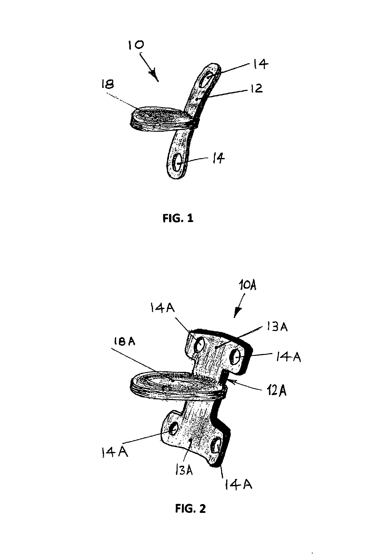
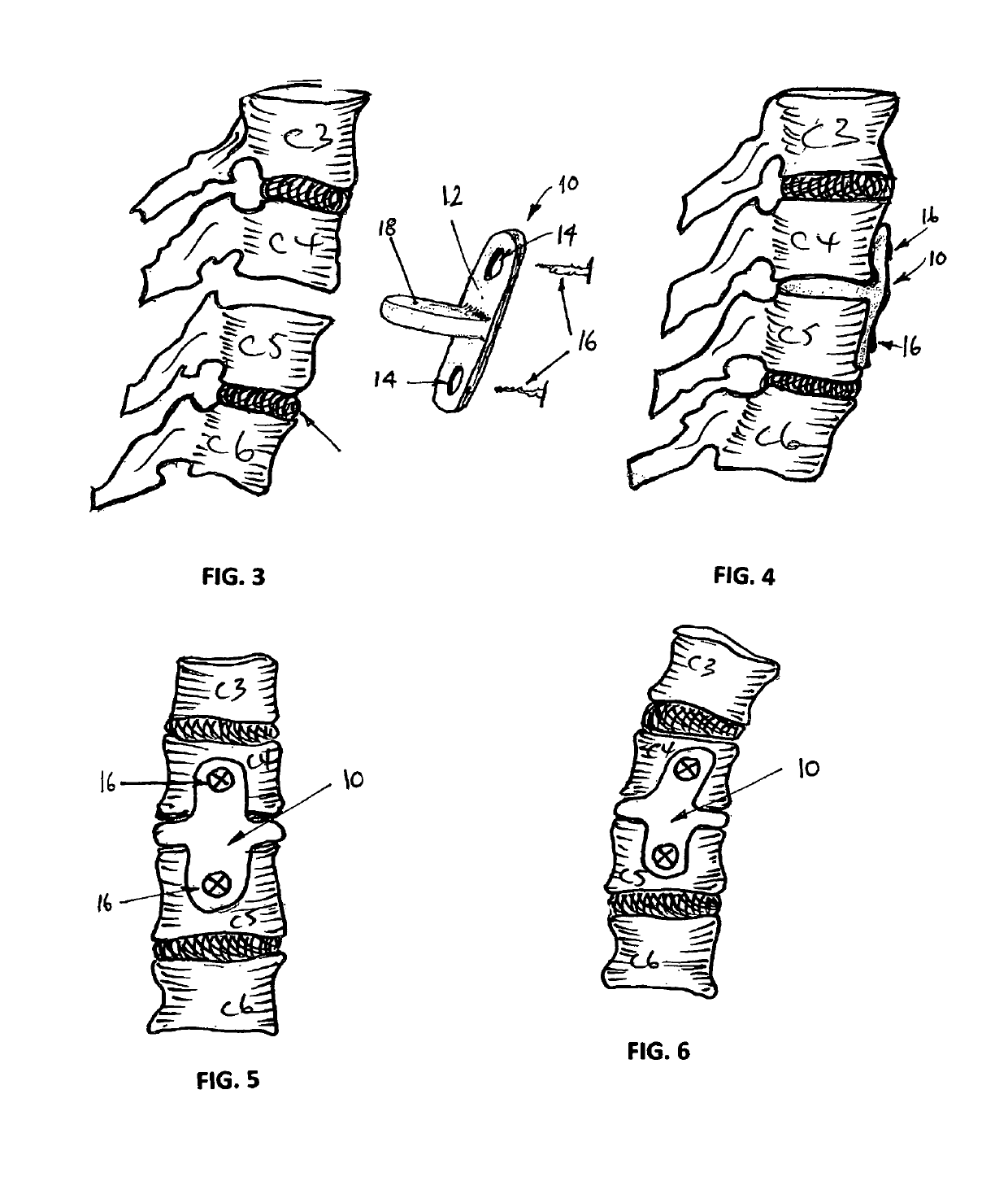
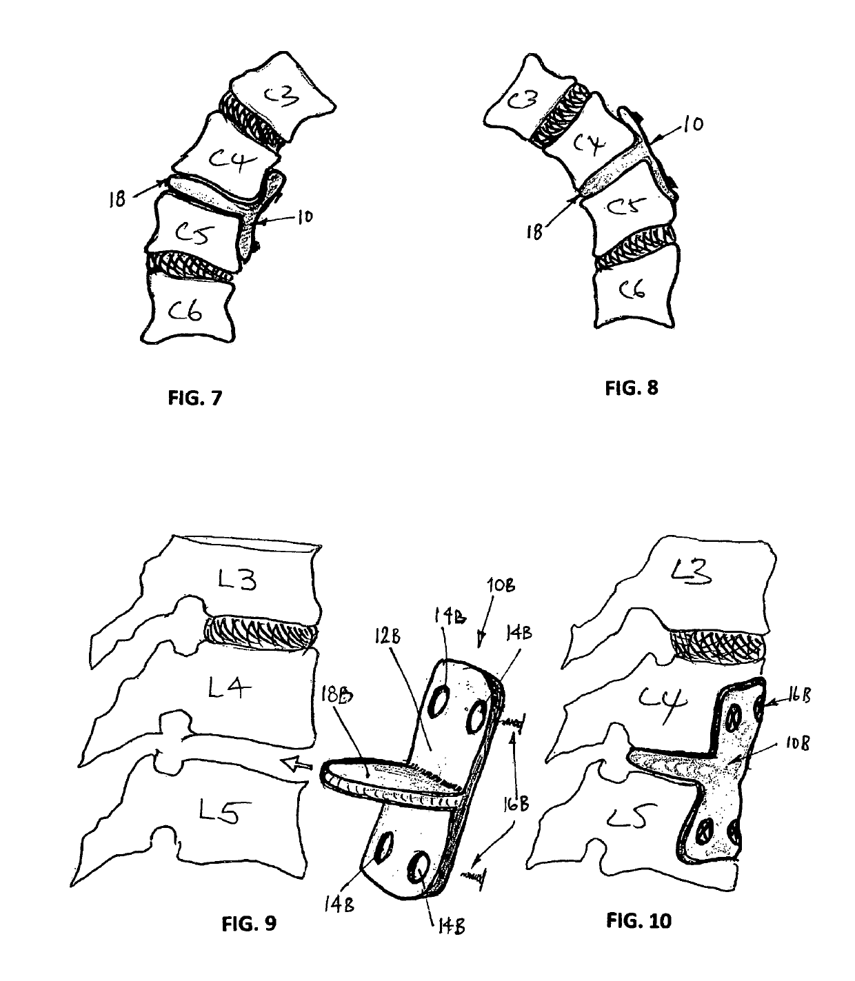
[0265]In one example of a surgical procedure, an intervertebral disc implant device in the form of a single bracket and pad, such as those set forth in embodiment 1, was deployed between two selected and adjacent vertebrae in the spinal column.

[0266]In this procedure, the degenerated intervertebral disc was first surgically removed from the spinal column of the patient, before inserting the bracket and pad.

[0267]Firstly the surgeon supported the two selected and adjacent vertebrae of the patient, using suitable clamping and jigs. The surgeon then removed the degenerated natural disc from between the two supported vertebrae using suitable surgical implements.

[0268]Once the area was clean / clear of the natural disc, the surgeon inserted into the intervertebral disc space the pad between the two adjacent vertebrae. Once the pad was in a suitable location, the surgeon secured opposite ends of the bracket to respective anterior faces of the adjacent two vertebrae, using one (or more) surg...


PUM


Abstract

An intervertebral disc implant device (10) is arranged to be positioned with respect to at least one disc space that is respectively located between at least two adjacent vertebrae (e.g. C4 & C5). The device comprises a connector (12) that extends between and interconnects the at least two adjacent vertebrae. The device also comprises at least one pad (18) that is integrally formed with and from the same material as the connector to extend laterally therefrom. The at least one pad is configured for location with respect to a respective disc space between the at least two adjacent vertebrae. The material for the pad is continuous from side-to-side, from front-to-back and from a pad top surface to a pad bottom surface. A surgical procedure for deploying the device is also disclosed.

Description

CROSS REFERENCE TO RELATED APPLICATIONS[0001]This is a National Stage application of PCT / AU2015 / 000139, filed Mar. 11, 2015, and further claims priority to Australian patent application serial no. 2014900811, filed Mar. 11, 2014, and New Zealand patent application serial no. 622352, filed Mar. 19, 2014, the disclosures of which are incorporated herein by reference.TECHNICAL FIELD[0002]Disclosed is an artificial intervertebral disc implant device which may be used to replace diseased, prolapsed, fragmented or otherwise damaged intervertebral discs in the spinal columns of humans or animals. A surgical procedure for deploying the device is also disclosed.BACKGROUND ART[0003]One known surgical technique for correcting intervertebral disc damage or degeneration (and associated instability of the spinal column) involves surgically removing damaged disc material and fusing the vertebrae immediately above and below the damaged disc. In one form, this can be achieved by inserting, anteriorl...

Claims


Application Information

Patent Timeline
Patent Type & Authority Patents(United States)
IPC IPC(8): A61F2/44A61B17/70
CPCA61B17/7053A61B17/7059A61B17/7061A61F2/4455A61F2002/30014A61F2002/4495A61F2/4465A61F2002/30578A61F2002/30604A61F2002/305A61F2002/30331A61F2002/30289A61F2002/449A61F2/442A61B17/70A61F2/44
Inventor MACLENNAN, DOUGLAS STAFFORD
Owner MACLENNAN DOUGLAS STAFFORD
Why Eureka
Try Eureka