Printing Apparatus

a printing apparatus and printing technology, applied in printing, typewriters, thin material handling, etc., can solve the problems of ink jet recording apparatus, difficulty in adjusting the printing speed, so as to suppress the deterioration of transport accuracy and improve printing quality. , the effect of simple mechanism

Active Publication Date: 2019-09-03
SEIKO EPSON CORP
View PDF10 Cites 0 Cited by
  • Summary
  • Abstract
  • Description
  • Claims
  • Application Information

AI Technical Summary

Benefits of technology

[0075]With the printing apparatus according to one embodiment, the following advantageous effects can be obtained. The printing apparatus 10 according to the embodiment includes the supply section 40, the transport section 60, and the printing section 70. The supply section 40 supports a plurality of rolls RA around which roll-paper strips M are wound and supplies the roll-paper strips M. The transport section 60 applies transporting forces to the supplied roll-paper strips M and transports the roll-paper strips M. The printing section 70 performs printing onto the transported roll-paper strips M. In short, the printing apparatus 10 according to the embodiment can perform printing in parallel on a plurality of roll-paper strips M supplied from rolls RA. In addition, the printing apparatus 10 includes the rotational drive devices (the first motor 442 and the second motor 452) that serve as the tension-imparting section 440 that imparts respective tensile forces individually to a plurality of roll-paper strips M against the transporting forces acting on the roll-paper strips M. Thus, in the case that the transporting rate (feed rate) under a predetermined transporting force may become different depending on a transported roll-paper strip M, the difference in the transporting rate (feed rate) can be corrected by imparting a tensile force, which acts against the transporting force, individually to the roll-paper strip M. As a result, the transport accuracy for a plurality of roll-paper strips M can be further improved, and differences in the quality of printed images can be suppressed. By imparting individualized tensile forces to the multiple roll-paper strips, the transport rate of the multiple roll-paper strips can be essentially equalized notwithstanding the different media characteristics.
[0076]Moreover, the transport section 60 has common transport rollers (the drive roller 61 and the idler roller 62) that transport a plurality of roll-paper strips M in parallel, and the printing section 70 has the common printing head 71 that performs printing onto a plurality of the roll-paper strips M. In other words, the printing apparatus 10 that can perform printing in parallel on a plurality of roll-paper strips M supplied from rolls RA can be constructed with a simple mechanism. As described above, the printing apparatus 10 includes the tension-imparting section 440 that imparts respective tensile forces individually to a plurality of roll-paper strips M against transporting forces acting on the roll-paper strips M. Thus, even with such a simple mechanism, the printing apparatus 10 can suppress deterioration in the transport accuracy for a plurality of roll-paper strips M, thereby enabling higher quality printing.
[0077]The tension-imparting section 440 imparts amounts of tensile force that are set according to types of roll-paper strips M individually to corresponding roll-paper strips M. This enables appropriate correction when amounts of slip in transport by the transport section 60 become different between the types of roll-paper strips M (e.g., due to difference in material, width, etc.).
[0078]Moreover, the tension-imparting section 440 has the rotational drive devices (first motor 442, second motor 452) that rotationally drive rolls RA in the supply section 40. The tension-imparting section 440 controls respective tensile forces applied individually to a plurality of roll-paper strips M by controlling driving torques for driving the rotational drive devices. In other words, in the supply section 40, the tension-imparting section 440 causes the rotational drive devices to supply roll-paper strips M to the printing section 70 (or to increase / decrease the supply loads). While doing so, the tension-imparting section 440 controls driving torques that drive the rotational drive devices and thereby controls respective tensile forces that are individually applied to a plurality of roll-paper strips M. According to this configuration, the tension-imparting section 440 can be formed as part of the function of the supply section 40. In other words, the tension-imparting section 440 can be formed by using a function of the supply section 40. The tension-imparting section can be integrated into the supply section 40. Consequently, the printing apparatus 10 that can perform printing on a plurality of roll-paper strips M in parallel can be constructed efficiently while enabling higher quality printing.
[0079]In addition, the tension-imparting section 440 (first motor 442, second motor 452) is disposed upstream of the transport section 60 on the transport path on which roll-paper strips M are transported. Thus, the tension-imparting section 440 can impart tensile forces that act on the roll-paper strips M in a direction opposite to the transporting forces applied by the transport section 60. In other words, when the transport section 60 transports a plurality of roll-paper strips M and the amounts of slip (transport errors) of the transport section 60 become different between the roll-paper strips M, tensile forces acting in the direction opposite to the transporting forces are imparted to respective (e.g., one or more) roll-paper strips M in such a manner that the amounts of slip in transport by the transport section 60 (transport errors) become the same, thereby correcting the transport errors.
[0080]Note that embodiments of the invention are not limited to the embodiment described above, and various modifications and alternations can be added to the embodiment. Modification examples will be described below. Like numerals will be used for elements similar to those of the above embodiment, thereby duplicated description will be omitted.Modification

Problems solved by technology

However, the printing apparatus (ink jet recording apparatus) disclosed by JP-A-2003-326781 sometimes encounters a problem.
This may lead to a difference in the quality of printed images among the roll-paper strips or may lead to an inability to obtain the best-quality print images on each of the roll-paper strips.
As a result, the transporting accuracy of the printing media with respect to the common printing head may become different from each other.

Method used


Image

  • Printing Apparatus
  • Printing Apparatus
  • Printing Apparatus

Examples


embodiment 1

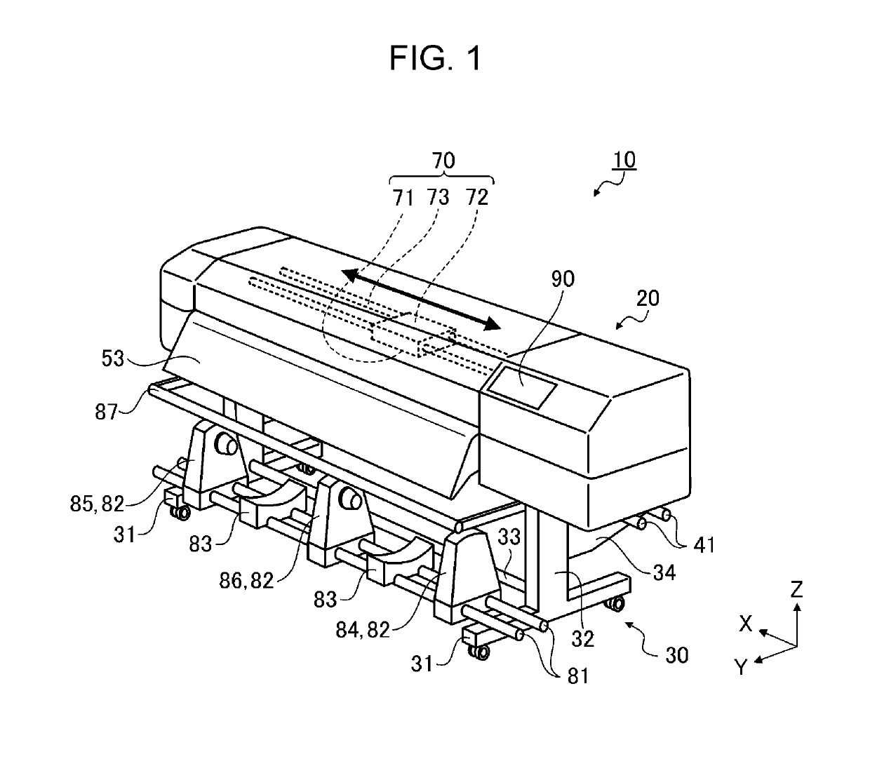
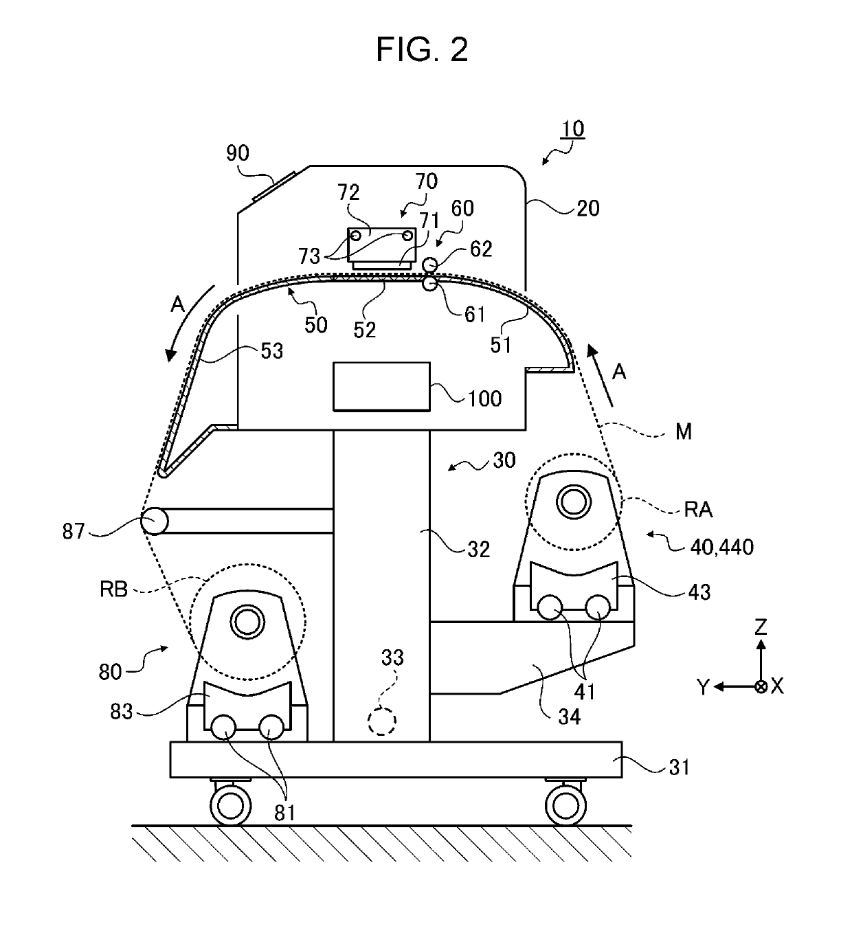
[0038]FIG. 1 is a perspective view illustrating an example configuration of a printing apparatus 10, and FIG. 2 is a cross-sectional side view of the printing apparatus 10. The printing apparatus 10 may be an ink jet printer that prints desired images onto a long roll-paper strip M that is supplied as a printing medium in a form of rolled paper (i.e., a roll). The printing apparatus 10 includes a housing 20 that is shaped like a box in one example and a housing support 30 that supports the housing 20.

[0039]As illustrated in FIG. 2, the printing apparatus 10 also includes, in a transport direction A of a roll-paper strip M, a supply section 40 for supplying a roll-paper strip M that is wound into a roll RA, a medium support section 50 for supporting the roll-paper strip M, a transport section 60 for transporting the roll-paper strip M by providing the roll-paper strip M with a transporting force, a printing section 70 for performing printing onto the roll-paper strip M, and a winding...

modification example 1

[0081]In one embodiment, when conducting printing, a user (operator) of the printing apparatus 10 specifies a type of roll-paper strip M via the input section (operation unit 90). The control unit 100 obtains the amount of tensile force from the data table that corresponds to the type of roll-paper strip M specified by the user and applies the obtained tensile force for control. However, the printing apparatus 10 is not limited to such a configuration or a method. For example, the printing apparatus 10 may include a section for recognizing the type of roll-paper strip M, and the tension-imparting section 440 may individually impart a predetermined amount of tensile force according to the recognized type of roll-paper strip M to the corresponding roll-paper strip M.

[0082]FIG. 6 is a cross-sectional side view illustrating an example configuration of a printing apparatus 10. A printing apparatus 10 according to the present modification example includes a medium recognition section 200 ...

modification example 2

[0086]A printing apparatus 10 according to the modification example 2 includes a width detecting section 300 for detecting the widths of installed roll-paper strips M in addition to the printing apparatus 10. The printing apparatus 10 according to the present modification example is suitable when a limited number of texture types of the roll-paper strips M is used. In other words, the width detecting section is useful at least when the roll-paper strip M is mostly replaced with a different width type while the texture type of the roll-paper strip M is not changed often.

[0087]The width detecting section 300 includes a light-emitting / receiving device 301 that emits light to the roll-paper strips M transported on the transport path and receives reflected light of the light that has been emitted. The width detecting section 300 also includes a detection processing portion 302 that processes results (photodetection signal) from the reflected light that is received. The light-emitting / rec...


PUM


Abstract

The printing apparatus includes a supply section that supports a plurality of rolls into which roll-paper strips are wound and supplies the roll-paper strips, a transport section that applies respective transporting forces to the supplied roll-paper strips and transports the roll-paper strips, a printing section that performs printing onto the transported roll-paper strips, and a tension-imparting section that individually imparts respective tensile forces to a plurality of roll-paper strips against the transporting forces.

Description

CROSS-REFERENCE TO RELATED APPLICATIONS[0001]The present application claims priority to Japanese Patent Application No. 2017-030768, filed Feb. 22, 2017, which is hereby incorporated by reference in its entirety.BACKGROUND1. Technical Field[0002]Embodiments of the present invention relate to a printing apparatus that can perform printing on a plurality of printing media in parallel.2. Related Art[0003]Printing apparatuses that can simultaneously print on a plurality of printing media in parallel are known. For example, JP-A-2003-326781 discloses a printing apparatus (an ink jet recording apparatus) that includes a plurality of supply rolls that supply printing media (strips of paper). The printing apparatus simultaneously prints on the printing media supplied from respective supply rolls. The printing apparatus enables a plurality of roll-paper strips (supply rolls) to be set on a single spindle (shaft). The roll-paper strips are transported to a printing region (or typing region) b...

Claims


Application Information

Patent Timeline
Patent Type & Authority Patents(United States)
IPC IPC(8): B41J11/00B41J15/04B41J15/18B41J15/16
CPCB41J15/165B41J11/009B41J15/04B41J15/16B41J15/18B41J3/62B65H20/02B65H23/1888B65H43/00B65H2701/1133B65H2801/03B41J15/22
Inventor TAKAHASHI, YOJIKOBAYASHI, MASAKIKATO, JUNYAHAMA, YOSHIKAZU
Owner SEIKO EPSON CORP
Why Eureka
Try Eureka