Augmented vision system with active welder guidance

a vision system and active technology, applied in the field of augmented vision systems with active welder guidance, can solve the problems of difficulty in monitoring and maintaining these important parameters for welding operators, and achieve the effect of improving the safety of welding operators

Active Publication Date: 2019-09-10
ILLINOIS TOOL WORKS INC
View PDF65 Cites 0 Cited by
  • Summary
  • Abstract
  • Description
  • Claims
  • Application Information

AI Technical Summary

Problems solved by technology

Even experienced welding operators, however, often have difficulty monitoring and maintaining these important parameters throughout welding processes.

Method used


Image

  • Augmented vision system with active welder guidance
  • Augmented vision system with active welder guidance
  • Augmented vision system with active welder guidance

Examples


Embodiment Construction

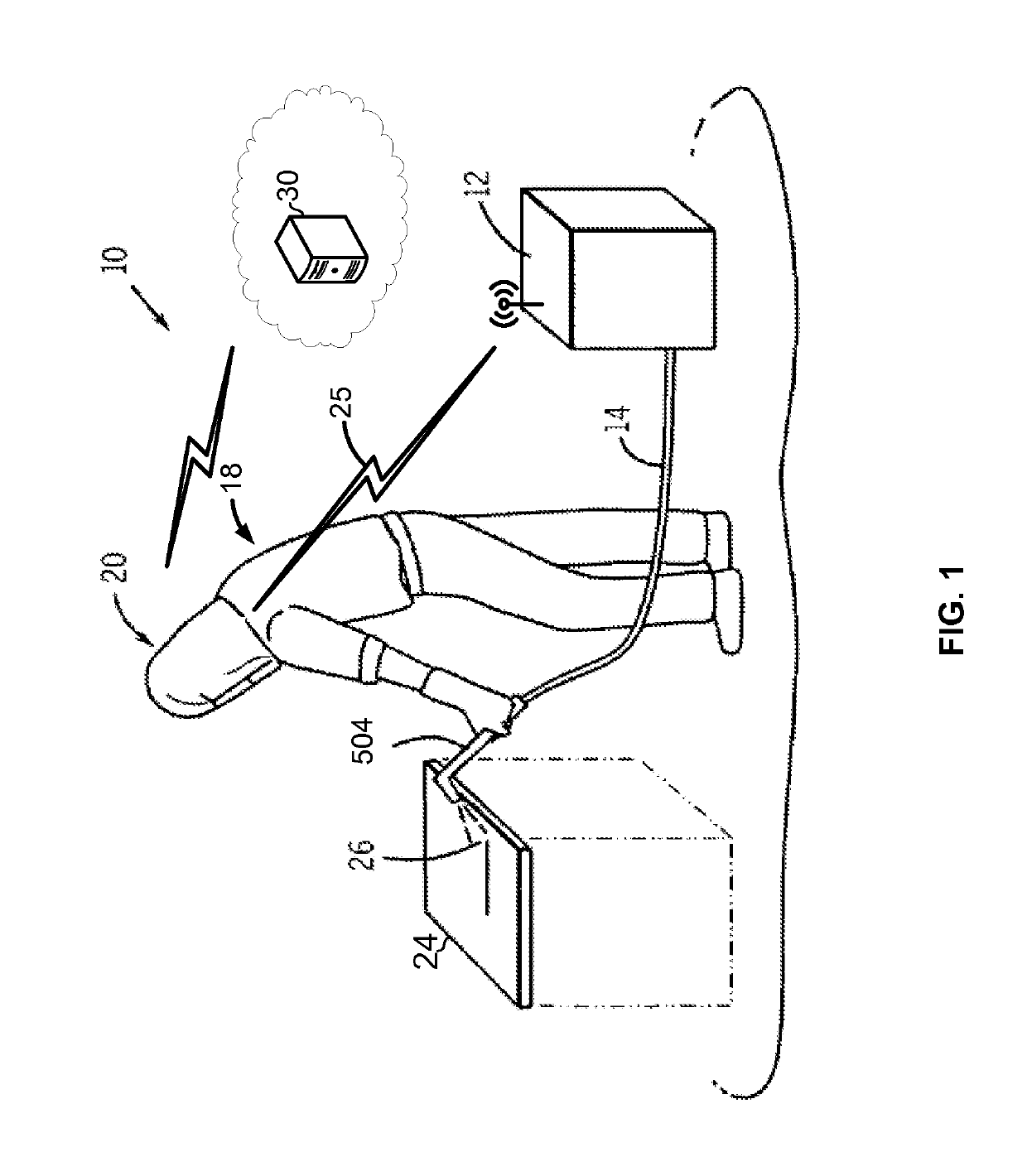
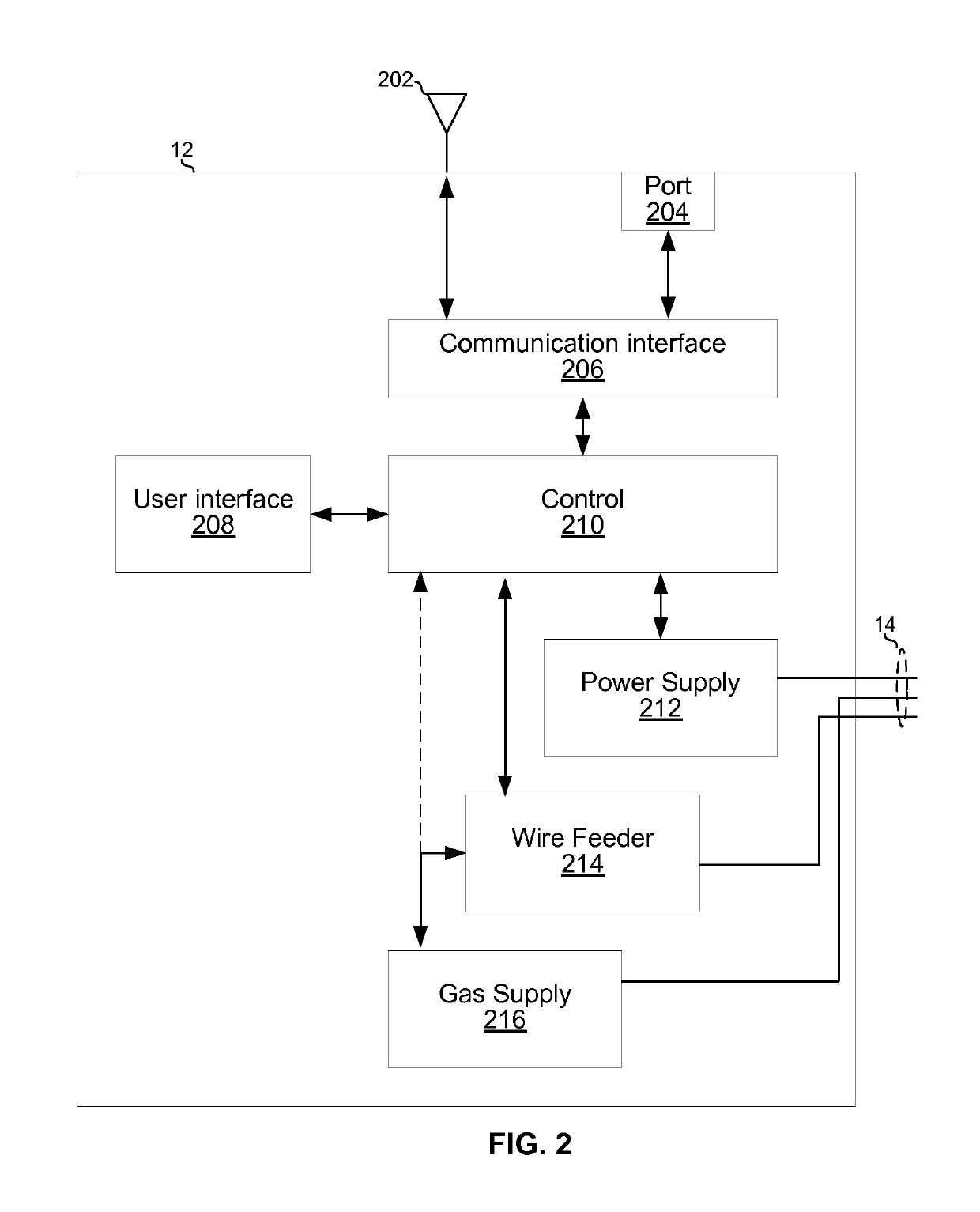
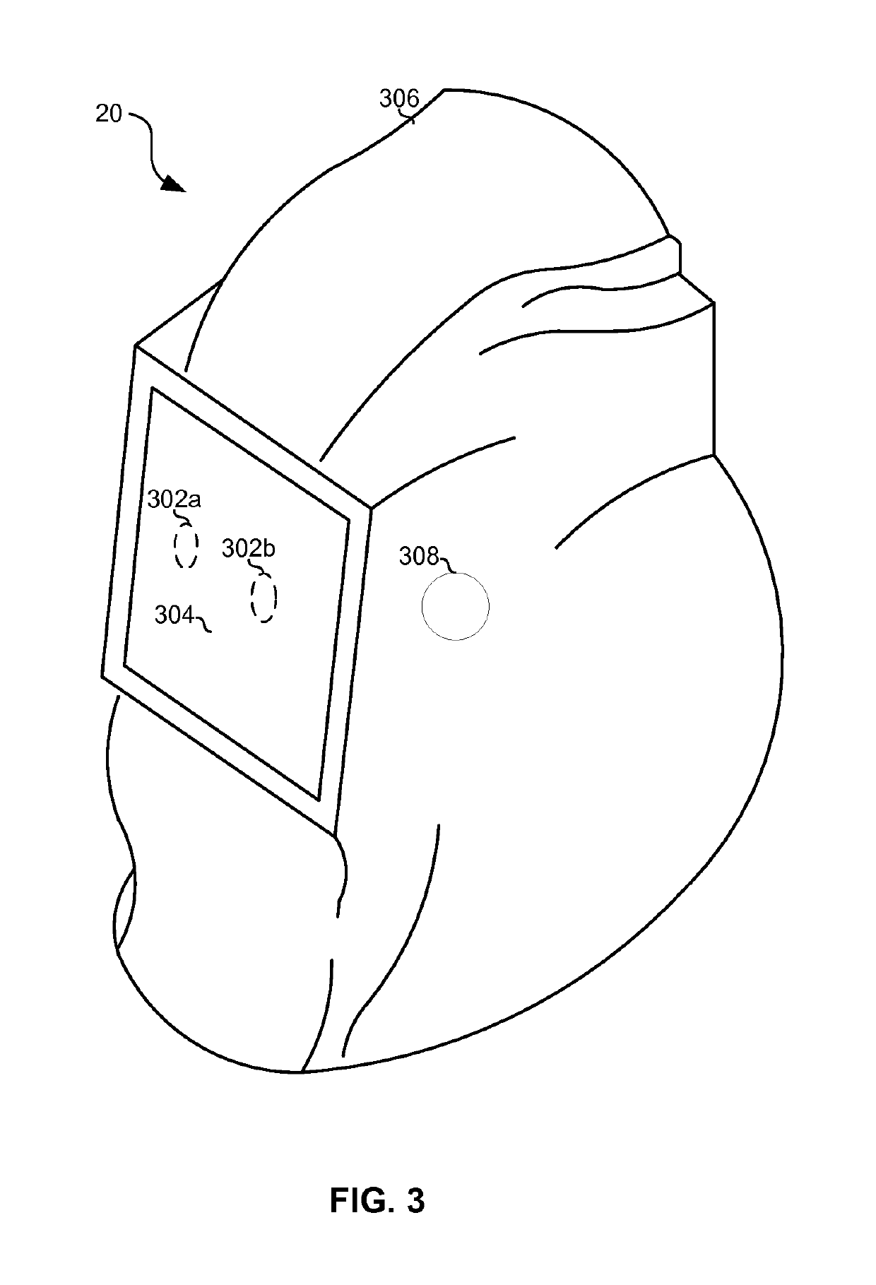
[0013]Referring to FIG. 1, there is shown an example welding system 10 in which an operator 18 is wearing welding headwear 20 and welding a workpiece 24 using a torch 504 to which power or fuel is delivered by equipment 12 via a conduit 14. The equipment 12 may comprise a power or fuel source, optionally a source of an inert shield gas and, where wire / filler material is to be provided automatically, a wire feeder. The welding system 10 of FIG. 1 may be configured to form a weld joint 512 by any known technique, including flame welding techniques such as oxy-fuel welding and electric welding techniques such as shielded metal arc welding (i.e., stick welding), metal inert gas welding (MIG), tungsten inert gas welding (TIG), and resistance welding.

[0014]Optionally in any embodiment, the welding equipment 12 may be arc welding equipment that provides a direct current (DC) or alternating current (AC) to a consumable or non-consumable electrode 16 (better shown, for example, in FIG. 5C) o...


PUM

PropertyMeasurementUnit
viewing distanceaaaaaaaaaa
distanceaaaaaaaaaa
image processingaaaaaaaaaa

Abstract

Welding headwear comprises a display operable to present images for viewing by a wearer of the welding headwear, and comprises circuitry operable to determine an identifier associated with a workpiece, retrieve, from memory, welding work instructions associated with the identifier, and generate the images for presentation on the display based on said work instructions.

Description

PRIORITY CLAIM[0001]This application claims priority to the following application(s), each of which is hereby incorporated herein by reference:[0002]U.S. provisional patent application 62 / 121,853 titled “AUGMENTED VISION SYSTEM WITH ACTIVE WELDER GUIDANCE” filed on Feb. 27, 2015.BACKGROUND[0003]Welding is a process that has increasingly become ubiquitous in all industries. While such processes may be automated in certain contexts, a large number of applications continue to exist for manual welding operations, the success of which relies heavily on the proper use of a welding gun or torch by a welding operator. For instance, improper torch angle, contact tip-to-work distance, travel speed, and aim are parameters that may dictate the quality of a weld. Even experienced welding operators, however, often have difficulty monitoring and maintaining these important parameters throughout welding processes.BRIEF SUMMARY[0004]Methods and systems are provided for weld output control by a weldi...

Claims


Application Information

Patent Timeline
Patent Type & Authority Patents(United States)
IPC IPC(8): B23K37/00B23K9/32B23K9/095G05B19/409G06F3/03
CPCB23K37/006B23K9/0956B23K9/322G05B19/409Y02P90/10G05B2219/32014G06F3/0304G05B2219/45135G05B2219/35487G05B2219/31304Y02P90/02
Inventor ALBRECHT, BRUCEBEESON, RICHARDBECKER, WILLIAM J.
Owner ILLINOIS TOOL WORKS INC
Why Eureka
Try Eureka