
Head mounted display

a display and head technology, applied in the direction of display/control unit casings, instruments, casings of electrical apparatus, etc., can solve the problem that users may feel uncomfortable wearing the display head, and achieve the effect of comfortable user experien

Active Publication Date: 2019-09-10
HTC CORP
View PDF11 Cites 1 Cited by
  • Summary
  • Abstract
  • Description
  • Claims
  • Application Information

AI Technical Summary

Benefits of technology

[0004]The disclosure relates to a head mounted display capable of automatically adapting the distribution of the wearing pressure when the user is tightening up the display, so as to create a more comfortable user experience.
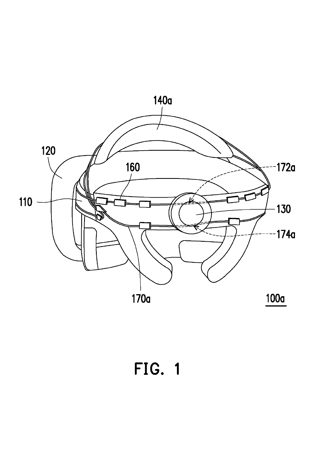
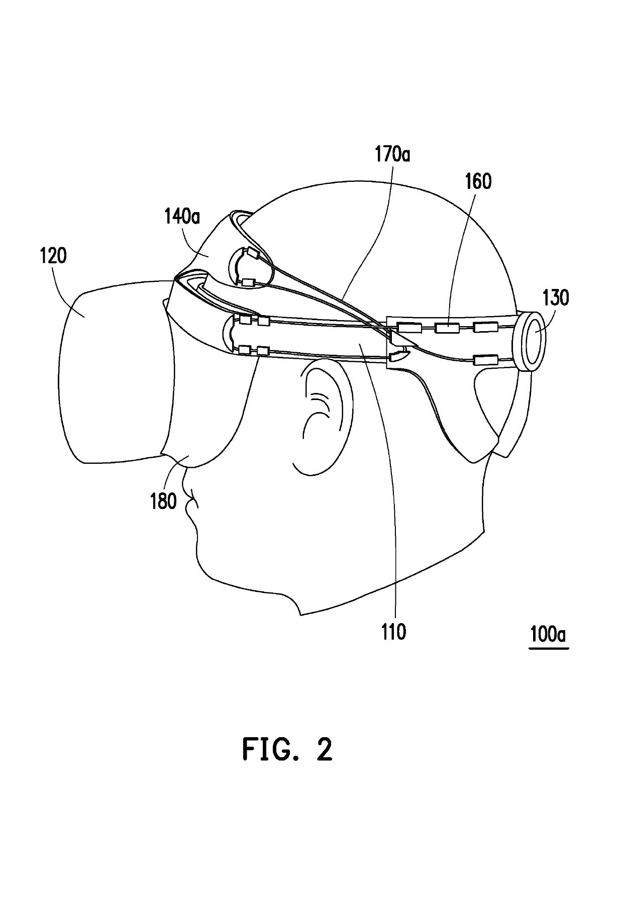
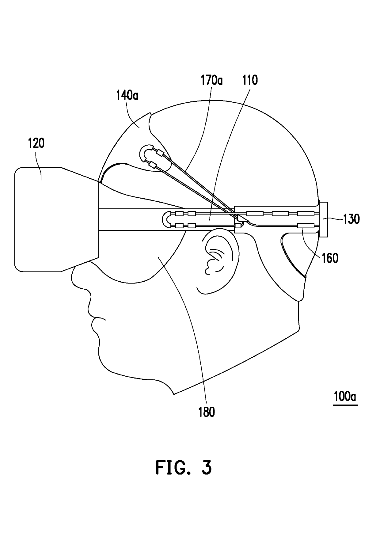
[0007]Based on the above, in the head mounted display of the disclosure, the degree of tightening and loosening when the head mounted display is being worn is adjusted by the lace. Besides, because the retractable portion of the lace is nearer to the display part and is rather away from the forehead pad or the rear pad, when the magnitude of tension of the lace is being adjusted at the retractable portion, the tension near the forehead pad or the rear pad is smaller than the tension near the display part, so as to avoid overly pressurize the user's frontal bone or occipital bone and to thereby create a more comfortable user experience.

Problems solved by technology

However, since the head shape differs person by person, some users may feel uncomfortable when wearing the head mounted display because the head mounted display does not fit the contour of their head.

Method used


Image

  • Head mounted display
  • Head mounted display
  • Head mounted display

Examples


Embodiment Construction

[0015]It is to be understood that both the foregoing and other detailed descriptions, features and advantages are intended to be described more comprehensively by providing an embodiment accompanied with figures hereinafter. In this regard, directional terminology, such as “top,”“bottom,”“left,”“right,”“front,” and “back,” is used with reference to the orientation of the figure(s) being described. Therefore, the directional wording is used to illustrate rather than limit the disclosure. Moreover, the same or similar reference numerals represent the same or similar elements in the following embodiments.

[0016]FIG. 1 is a schematic three-dimensional view of a head mounted display according to an embodiment of the invention. FIG. 2 is a schematic view showing the head mounted display of FIG. 1 worn on a user's head. FIG. 3 is a schematic view showing the head mounted display of FIG. 1 worn on a user's head from a side perspective. Referring to FIG. 1 to FIG. 3, a head mounted display 10...


PUM


Abstract

A head mounted display including a main strap, a display part, an adjusting mechanism, a forehead pad, a plurality of holders and a lace is provided. The main strap surrounds a user's head. The display part is connected to the main strap and corresponds to the user's eyes. The adjusting mechanism is disposed on the main strap. The forehead pad corresponds to the user's frontal bone. The holders are disposed on the main strap and the forehead pad. A path of the lace in sequence passes through a retractable portion, a portion of the main strap near a first side of the display part, a first side of the forehead pad, a fixed portion of the lace, a second side of the forehead pad and a portion of the main strap near a second side of the display part. The adjusting mechanism connects the retractable portion and is adapted to adjust a magnitude of tension of the lace at the retractable portion. The lace is fixed at the main strap and the forehead pad by the holders.

Description

CROSS-REFERENCE TO RELATED APPLICATION[0001]This application claims the priority benefit of U.S. provisional application Ser. No. 62 / 581,782, filed on Nov. 6, 2017. The entirety of the above-mentioned patent application is hereby incorporated by reference herein and made a part of this specification.BACKGROUND OF THE INVENTIONField of the Invention[0002]The disclosure relates to a head mounted display, and more particularly, to a head mounted display capable of adapting the wearing pressure automatically.Description of Related Art[0003]Virtual reality (VR) system has become a really popular technology in the market. After putting on the head mounted display (HMD) with head straps or other accessories for holding the device on the head, the user can watch three-dimensional images with the display part located in front of the eyes and is granted a more vivid and immersive feeling. To ensure that the head mounted display can be worn on the user's head fittingly, Velcro or gear structur...

Claims


Application Information

Patent Timeline
Patent Type & Authority Patents(United States)
IPC IPC(8): H05K7/02H05K7/04H05K5/02H05K5/00G02B27/00
CPCH05K5/0217H05K5/0086H05K5/0017G02B27/00G02B27/0176G02B2027/0178G02B2027/0169
Inventor CHANG, LI-HSUNOU, KUAN-YING
Owner HTC CORP
Learn More